
Stacking mold with ejecting rods

A technology of ejector and mold, applied in the field of stacking molds, can solve the problems of scratching of ejector, impact on shell parts, unqualified structure, etc., and achieve the effect of convenient use and soft effect

Inactive Publication Date: 2014-04-23
SHENGYANG PRECISION MOLD KUSN
View PDF2 Cites 1 Cited by
  • Summary
  • Abstract
  • Description
  • Claims
  • Application Information

AI Technical Summary

Problems solved by technology

[0002] The housing of electronic products is usually molded by thermocompression molding. When the housing is injected, the smaller structure and the part with lines have higher requirements for injection molding, and the process of heating, exhaust, cooling and ejection is required during injection molding. , Each process will produce unqualified conditions such as structure, which will affect the position deviation and misalignment of the mutual ferrules and screw holes of each shell
The cooling process requires fast and low temperature, and the ejection process also requires a suitable angle and tools. During the ejection process, the ejector pin is often scratched and the injection molded product will be damaged.

Method used


Image

  • Stacking mold with ejecting rods
  • Stacking mold with ejecting rods

Examples


Embodiment Construction

[0015] Specific embodiments of the present invention will be further described in detail below.

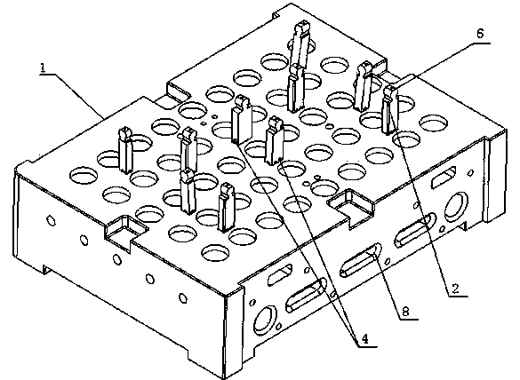
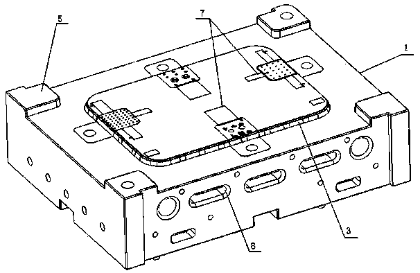
[0016] Such as figure 1 with figure 2 As shown, a stacked mold with ejector pins of the present invention includes: a body 1, a cavity 3 located at the top of the body, and several ejector pins 2 located at the bottom of the body. The ejector pins 2 protrude from the bottom of the body 1, and the ejector pins 2 is set on the bottom of the body 1 through the return pin 4, and the ejector pin hole 7 corresponding to the position of the ejector pin 2 is provided on the cavity 3. The main body 1 is a cuboid structure, and four corners of the top of the main body 1 are respectively provided with a pillar 5 , and the height of the pillar 5 is less than the length of the ejector rod 2 . Several ejector pins 2 are arranged on the bottom of the body 1 in axisymmetric manner, two ejector pins 2 are located on the axis of axisymmetrical axis, and four ejector pins 2 are arranged at both e...


PUM


Abstract

The invention discloses a stacking mold with ejecting rods. The stacking mold comprises a body, a cavity and a plurality of ejecting rods, wherein the cavity is positioned at the top part of the body; the plurality of ejecting rods are positioned at the bottom part of the body. The stacking mold is characterized in that the ejecting rods extend out of the bottom part of the body and are arranged at the bottom part of the body by return pins; the cavity is provided with ejecting rod holes corresponding to the positions of the ejecting rods. The stacking mold disclosed by the invention has the advantages that the plurality of ejecting rods are arranged at the bottom part of the body in a manner of axisymmetric arrangement, so that the ejecting force can be uniformly applied to an injection molding product and the action of the ejecting force on the injection molding product is softer; simultaneously arc-shaped end surfaces arranged at the free ends of the ejecting rods are smoother, so that the surface of the injection molding product can not be scratched or the structure of the injection molding product can not be damaged; the other ends of the ejecting rods are connected at the bottom part of the body by the return pins and is rotatably vertical or parallel to the bottom part of the body, so that the use is convenient.

Description

technical field [0001] The invention relates to an injection mold, in particular to a stack mold with ejector pins for a notebook computer. Background technique [0002] The housing of electronic products is usually molded by thermocompression molding. When the housing is injected, the smaller structure and the part with lines have higher requirements for injection molding, and the process of heating, exhaust, cooling and ejection is required during injection molding. , Each process will produce unqualified conditions such as structure, which will affect the positional deviation and misalignment of the mutual ferrules and screw holes of each shell. The cooling process requires fast and low temperature, and the ejection process also requires a suitable angle and tools. During the ejection process, there are often cases where the ejector pin is scratched and the injection molded product will be damaged. Therefore, molds with reasonable and compact structural design, which can...

Claims


Application Information

Patent Timeline
Patent Type & Authority Applications(China)
IPC IPC(8): B29C45/26B29C45/40B29C45/73
CPCB29C45/401B29C45/26
Inventor 陈宗慧黄小兵杨振
Owner SHENGYANG PRECISION MOLD KUSN
Learn More