
Round Mark point positioning method based on connected region filtering

A technology of connecting areas and positioning methods, applied in the fields of instruments, character and pattern recognition, computer parts, etc., can solve the problems of large computer memory requirements, low precision, and high process requirements

Active Publication Date: 2014-04-16
宁波智能装备研究院有限公司
View PDF5 Cites 48 Cited by
  • Summary
  • Abstract
  • Description
  • Claims
  • Application Information

AI Technical Summary

Problems solved by technology

[0003] The purpose of the present invention is to solve the problems of Hough circle transformation in the traditional circular mark point positioning method, which has complicated noise calculation process, large demand for computer memory, slow execution speed, long detection time and low precision, and the traditional method is easily affected by the outside world. Environmental influences cause unsuccessful matching with the standard template, which affects the detection results, and this method has high requirements for the Mark process. For the slightly deformed circular Mark points, the detection accuracy cannot meet the requirements. A proposed method based on Locating Method of Circular Mark Points Based on Connected Region Filtering

Method used


Image

  • Round Mark point positioning method based on connected region filtering
  • Round Mark point positioning method based on connected region filtering
  • Round Mark point positioning method based on connected region filtering

Examples


specific Embodiment approach 1

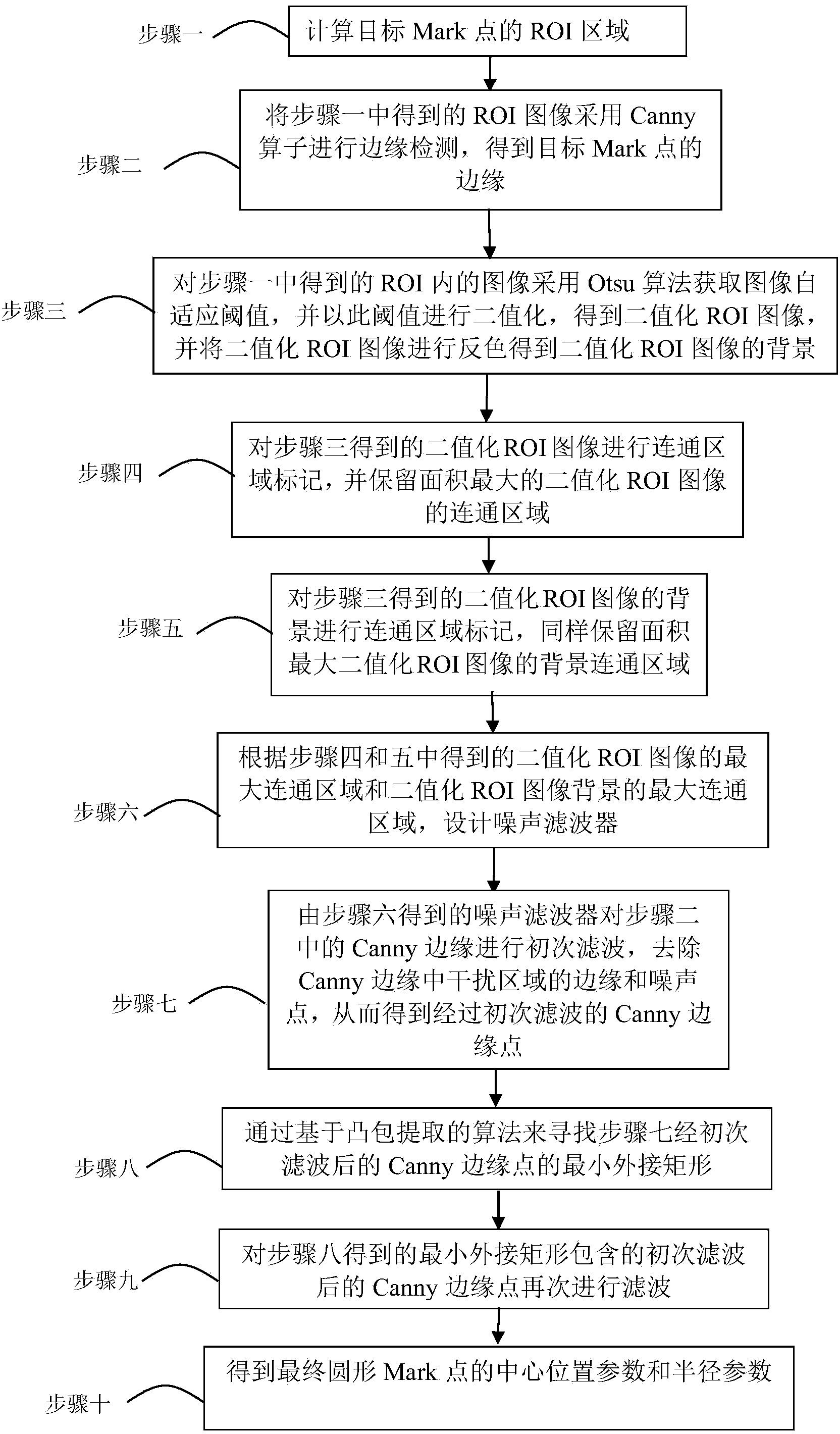
[0027] Specific embodiment one: a kind of positioning method of the circular mark point based on connected area filtering in this embodiment is prepared according to the following steps:

[0028] Step 1. Calculate the ROI (Region of Interest) area of ​​the target Mark point, where the ROI area is the target area of ​​interest; ROI reduces the size required for image calculation; in subsequent calculations, all calculations are performed in the ROI area of ​​​​the image, thereby reducing image processing time;

[0029] Step 2, using the Canny operator to perform edge detection on the ROI image obtained in step 1, to obtain the edge of the target Mark point, the edge of the Mark point may also contain some edges and noise in the interference area;

[0030] Step 3. Use the Otsu algorithm to obtain the image adaptive threshold for the image in the ROI obtained in step 1, and perform binarization with this threshold to obtain a binarized ROI image, and reverse the color of the bina...

specific Embodiment approach 2

[0040] Embodiment 2: The difference between this embodiment and Embodiment 1 is that the specific process of obtaining the background of the binarized image as described in step 3 and inverting the color of the binarized image is as follows:

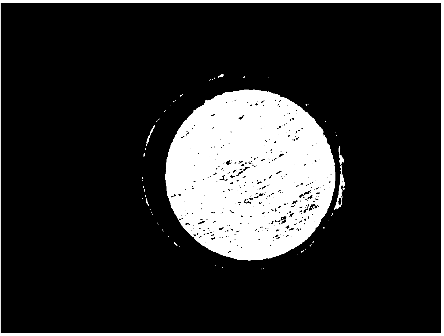
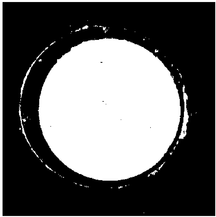
[0041] The background gray value of the binarized ROI image is reversed from 0 to 255, and then as the target to be processed, the connected region of the binarized ROI image is marked, and the connected region of the binarized ROI image with the largest area is reserved. Other steps and parameters are the same as those in Embodiment 1.

specific Embodiment approach 3

[0042] Specific implementation mode three: the difference between this implementation mode and specific implementation mode one or two is: in step 4, the process of obtaining the connected region of the binarized ROI image with the largest reserved area is:

[0043] (1) The ROI image is projected onto the abscissa and ordinate respectively;

[0044] (2) projected to the leftmost pixel of the maximum connected area of ​​the binarized ROI image corresponding to the pixel of the minimum value of the abscissa;

[0045] (3) The pixel point projected to the maximum value of the abscissa corresponds to the rightmost pixel point of the maximum connected region of the binarized ROI image;

[0046] (4) The pixel point projected to the minimum value of the ordinate corresponds to the pixel point at the bottom of the maximum connected region of the binarized ROI image;

[0047] (5) The pixel point projected to the maximum value of the ordinate corresponds to the pixel point on the top of...


PUM


Abstract

A round Mark point positioning method based on connected region filtering relates to positioning methods. The round Mark point positioning method based on the connected region filtering mainly solves the problem that traditional round Mark point positioning methods are complex in positioning algorithm, high in computer memory requirements, low in detecting time, low in detecting accuracy and prone to being affected by external environments to lead to template matching failure, meanwhile, have high Mark process requirements and cannot meet the detecting accuracy requirements for deformed round Mark points. The method comprises firstly, calculating the ROI (region of interest) of a target Mark point; secondly, obtaining the edge of the target point; thirdly, obtaining a binary ROI image; fourthly, retaining the ROI connected region with the maximum area; fifthly, retaining the ROI background connected region with the maximum area; sixthly, designing a noise filter; seventhly, obtaining filtering Canny edge points; eighthly, obtaining the minimum enclosing rectangle; ninthly, removing Canny edge defects; lastly, obtaining the central and radial parameters of the round Mark point. The round Mark point positioning method based on the connected region filtering is applied to the field of positioning methods.

Description

technical field [0001] The invention relates to a method for locating circular Mark points based on connected region filtering. Background technique [0002] At present, machine vision is more and more widely used in industrial inspection. Among them, the positioning of the reference mark point (Mark point) is extremely important, and the accuracy and speed of its positioning directly affect the accuracy and speed of the product. The most commonly used Mark point at this stage is a circle, and the traditional positioning methods include template matching method, Hough circle transformation, contour positioning method, etc. The detection speed of the template matching method is fast, but it is easily affected by the external environment. Changes in illumination may cause unsuccessful matching with the standard template and affect the detection results; The demand is large, the execution speed is slow, and the process requirements for Mark are relatively high. For circular Ma...

Claims


Application Information

Patent Timeline
Patent Type & Authority Applications(China)
IPC IPC(8): G06K9/00G06K9/32
Inventor 高会军周亚飞张欢欢邱一帆张叶梅李志成孙昊
Owner 宁波智能装备研究院有限公司
Learn More