Control Method of Spacecraft's Relative Orbit
A control method and relative orbit technology, applied in three-dimensional position/channel control and other directions, can solve problems such as low pointing accuracy, difficulty in maintaining time, easy exposure of identity, etc., to improve mission accuracy, simple analysis ideas, and difficult to expose identity Effect
- Summary
- Abstract
- Description
- Claims
- Application Information
AI Technical Summary
Problems solved by technology
Method used
Image
Examples
specific Embodiment approach 1
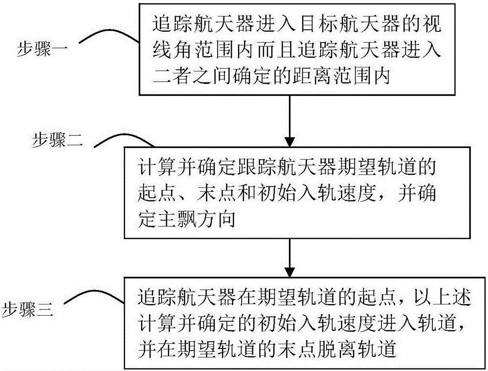
[0008] Specific implementation mode one: the following combination figure 1 This embodiment will be specifically described. This embodiment is realized through the following steps: 1. The tracking spacecraft enters the line-of-sight range of the target spacecraft and the tracking spacecraft enters the distance range determined between the two; 2. Calculate and determine the starting point of the expected orbit of the tracking spacecraft , the end point and the initial orbital velocity, and determine the main drift direction; 3. Track the spacecraft at the starting point of the desired orbit, enter the orbit at the initial orbital velocity calculated and determined above, and leave the orbit at the end point of the desired orbit, so that Complete the skimming maneuver of the target spacecraft.
[0009] (1) Explanation and customization of related concepts:
[0010] Geocentric inertial coordinate system (O-XYZ): The coordinate origin O is at the center of the earth's mass, the...
specific Embodiment
[0265] Specific embodiments: the following is an algorithm simulation verification experiment.
[0266] (1) Simulation parameters
[0267] 1.1 Target star orbit parameters
[0268] The target star is in the GEO orbit, and the hexagram of the initial orbit is: a 1 =4.225×10 7 m, e 1 = 0, i 1 =5°,Ω 1 = 31°, ω 1 = 0°, M0 1 = 0°.
[0269] Satellite perturbation coefficient parameters
[0270] Aerodynamic coefficient C D =1, resistance coefficient C d =2.2, reflection coefficient C r = 0.8.
[0271] 1.2 Glide parameters
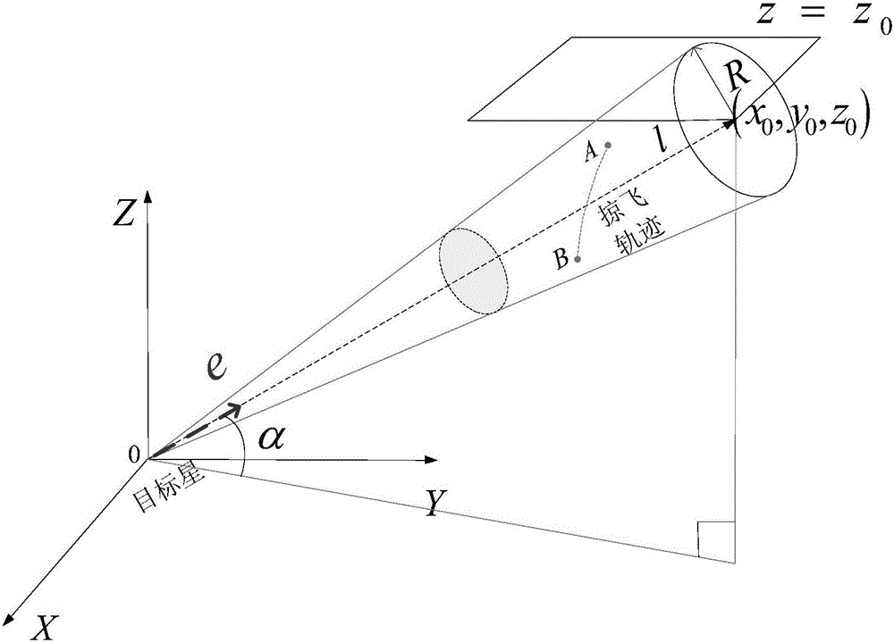
[0272] Target star line of sight direction vector e -hill =[-49647; -5194; 2863], the minimum distance R of the tracking star in the line of sight direction of the target star min = 50km, the farthest distance is R max =99.2km, line of sight angle θ=0.35°. The expected fly-by time is designed around 800s.
[0273] (2) Skimming trajectory design
[0274] Firstly, according to the design idea of section 0, the main drift direction is given as th...
PUM
 Abstract
Description
Claims
Application Information
 - R&D
- Intellectual Property
- Life Sciences
- Materials
- Tech Scout
- Unparalleled Data Quality
- Higher Quality Content
- 60% Fewer Hallucinations
Browse by: Latest US Patents, China's latest patents, Technical Efficacy Thesaurus, Application Domain, Technology Topic, Popular Technical Reports.
© 2025 PatSnap. All rights reserved.Legal|Privacy policy|Modern Slavery Act Transparency Statement|Sitemap|About US| Contact US: help@patsnap.com


