
Cassette optical line terminal equipment multiple passive optical fiber network card chip number identification method

A passive optical fiber network, optical line terminal technology, applied in data exchange networks, digital transmission systems, electrical components, etc., can solve problems such as increased product cost, error-prone, labor waste, etc., to reduce design difficulty, facilitate maintenance and Save and maintain simple effects

Inactive Publication Date: 2014-04-09
PHICOMM (SHANGHAI) CO LTD
View PDF6 Cites 3 Cited by
  • Summary
  • Abstract
  • Description
  • Claims
  • Application Information

AI Technical Summary

Problems solved by technology

[0008] 2. The control chip and other business chips are not on the same board:
[0013] When we design a box-type device with multiple identical PON cards, first of all, we will not increase the main control on each PON card, which will greatly increase the cost of the product, and it does not meet the characteristics of miniaturization; secondly , if the same software is used, only through the configuration of the hardware to realize the management of the PON chip by the master control, then the same PON card needs to be divided into different SLOT ID types for separate production during the material preparation or production process, and it is not convenient for production. line pipeline, and will bring additional costs for later maintenance and storage; again, when we use the same hardware solution, the image files of each PON chip are different, and the burn-in before production The recording or debugging process has brought a great waste of manpower, and it is also easy to make mistakes

Method used


Image

  • Cassette optical line terminal equipment multiple passive optical fiber network card chip number identification method
  • Cassette optical line terminal equipment multiple passive optical fiber network card chip number identification method

Examples


Embodiment Construction

[0034] The specific embodiments of the present invention will be further described below in conjunction with the accompanying drawings.

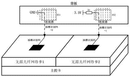
[0035] A method for identifying chip numbers of multiple passive optical fiber network cards for box-type optical line terminal equipment according to the present invention is applicable to box-type optical line terminal equipment. The box-type optical line terminal equipment mainly includes a main control card and several passive optical fiber network cards and backplate. Several passive optical network cards are connected to the main control card through a medium-independent interface (MII) circuit; each passive optical network card is provided with one or several passive optical network chips. The backplane is provided with several connectors, and each connector circuit is connected to a passive optical network chip.

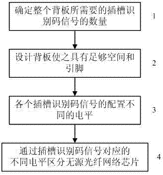
[0036] Such as figure 1 As shown, the method for identifying the chip number of the multi-passive optical fiber network...


PUM


Abstract

The invention discloses a cassette optical line terminal equipment multiple passive optical fiber network card chip number identification method. The method includes the following steps:1, the number of slot identification code signals required by the whole backplane is determined; 2, the backplane is designed to make the backplane has an enough space to place a pull-up resistor and / or a pull-down resistor for configuring slot identification code levels and has enough pins to connect a master control board and passive optical fiber network chips; 3, the pull-up resistor and / or the pull-down resistor are set according to the voltage of the backplane to configure different levels for each slot identification code signal; 4, and the passive optical fiber network chips are distinguished through the voltage difference between the slot identification code signals. According to the invention, the purpose of passive optical fiber network chip distinguishing is realized on the backplane of cassette equipment, and advantages of low overall design difficulty, reduced production cost and convenient post-maintenance and preservation can be realized.

Description

technical field [0001] The invention relates to a chip identification technology, in particular to a chip number identification method for multiple passive optical fiber network cards of box-type optical line terminal equipment. Background technique [0002] Most box-type devices are composed of main control boards, backplanes and service cards. Whether in box-type devices, medium-sized subrack devices or large subracks, the structure and hardware of each main control card, backplane and service card The designs are all exactly the same. The use of this equipment can shorten the cycle of product development, reduce the cost of development, reduce the investment in equipment for development and procurement, and can easily detect the problematic parts during the production and assembly process, and replace them separately. Only the part of the problem is sufficient, and there is no need to replace the entire product. With the extensive use of box-type equipment in communicat...

Claims


Application Information

Patent Timeline
Patent Type & Authority Applications(China)
IPC IPC(8): H04L12/26
Inventor 张贵清
Owner PHICOMM (SHANGHAI) CO LTD
Learn More