Semiconductor Optical Amplifier Cascaded Polarization Dominant State High Reliability Alignment Method and System

A technology of optical amplifier and alignment system, which is applied in the direction of laser devices, etc., to achieve the effects of dual-channel polarization multiplexing, cost reduction, and small angle error

Inactive Publication Date: 2017-01-04
BEIJING JIAOTONG UNIV
View PDF3 Cites 0 Cited by
  • Summary
  • Abstract
  • Description
  • Claims
  • Application Information

AI Technical Summary

Problems solved by technology

However, the prior art does not involve the alignment method of the polarization dominant state in the case of cascading multiple semiconductor optical amplifiers

Method used


Image

  • Semiconductor Optical Amplifier Cascaded Polarization Dominant State High Reliability Alignment Method and System
  • Semiconductor Optical Amplifier Cascaded Polarization Dominant State High Reliability Alignment Method and System
  • Semiconductor Optical Amplifier Cascaded Polarization Dominant State High Reliability Alignment Method and System

Examples


Embodiment 1

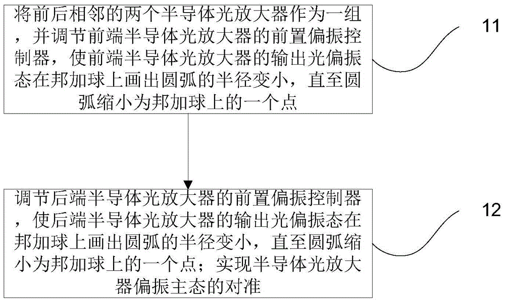
[0025] figure 1 It is a flow chart of a high-reliability alignment method for cascaded polarization dominant states of semiconductor optical amplifiers provided in Embodiment 1 of the present invention. Such as figure 1 As shown, the method mainly includes the following steps:

[0026] Step 11, take two adjacent semiconductor optical amplifiers as a group, and adjust the pre-polarization controller of the front-end semiconductor optical amplifier, so that the output light polarization state of the front-end semiconductor optical amplifier draws a circular arc on the Poincar sphere The radius gets smaller until the arc shrinks to a point on the Poincar sphere.

[0027] Specifically: first, adjust the control optical power of the front-end semiconductor optical amplifier, and observe the arc drawn by the polarization state of the output light on the Poincare sphere; then, adjust the front-end polarization controller of the front-end semiconductor optical amplifier to make the ...

Embodiment 2

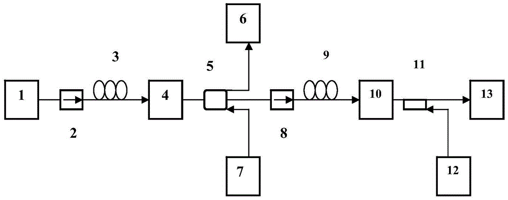
[0032] An embodiment of the present invention provides a semiconductor optical amplifier cascaded polarization main state high-reliability alignment system, the system mainly includes:

[0033] Semiconductor optical amplifiers with pre-optical isolators, pre-polarization controllers and post-couplers are cascaded in series; each stage of semiconductor optical amplifiers is connected to the pre-optical optical The isolator is connected to a reverse laser;

[0034] Wherein, the input end of the cascade string is also connected with a laser for inputting and aiming at the light source.

[0035] Further, each semiconductor optical amplifier is also connected to a polarization state analyzer via a rear coupler.

[0036] Further, the system includes several groups of semiconductor optical amplifiers connected in series with a pre-laser, a pre-optical isolator, a pre-polarization controller and a post-coupler.

[0037] Its schematic diagram can be found in the attached Figure 2-3...


PUM


Abstract

The invention discloses a method and a system for high-reliability alignment of a semiconductor optical amplifier cascading polarization principle state. The method comprises the steps of using two adjacent semiconductor optical amplifiers as one group, adjusting a front-arranged polarization controller of the front-end semiconductor optical amplifier to enable the radius of a circular arc drawn by an output light polarization state of the front-end semiconductor optical amplifier on a Poincare sphere to be small till the circular arc is reduced to be a point on the Poincare sphere; adjusting a front-arranged polarization controller of the rear-end semiconductor optical amplifier to enable the radius of a circular arc drawn by an output light polarization state of the rear-end semiconductor optical amplifier on the Poincare sphere to be small till the circular arc is reduced to be a point on the Poincare sphere; achieving alignment of the semiconductor optical amplifier cascading polarization principle state. By adopting the method, operation of a multiplexing system is simplified and known, the cost is reduced, and a good pushing role is played on the development of an all optical network and a polarization multiplexing technology.

Description

technical field [0001] The present invention relates to the technical field of semiconductor optical amplifiers, in particular to a highly reliable alignment method and system for cascaded polarization main states of semiconductor optical amplifiers. Background technique [0002] At present, high-speed and large-capacity communication systems have become an inevitable trend, and polarization multiplexing is a development path. The polarization dominant states of semiconductor optical amplifiers are of great significance to the realization of optical polarization multiplexing technology. [0003] When the polarization state of the input light is aligned with the polarization main state of the semiconductor optical amplifier, the polarization state of the output light of the semiconductor optical amplifier does not change with the change of the operating parameters such as the injection current of the semiconductor optical amplifier or the control optical power. On this basis...

Claims


Application Information

Patent Timeline
Patent Type & Authority Patents(China)
IPC IPC(8): H01S3/23
Inventor 朱哲盛新志冯震毛亚雅王苒高松
Owner BEIJING JIAOTONG UNIV
Why Eureka
Try Eureka