
A motion control system and control method for an electromagnetic rail-type mobile robot

A motion control system, a technology for mobile robots, applied in two-dimensional position/channel control and other directions, can solve the problems of immature robot motion control, error-prone track switching, and difficulty in precise positioning, so as to improve power transmission efficiency and solve signal problems. Dead zone problem, effect of magnetic coupling resonance strength guarantee

Active Publication Date: 2017-05-17
CHANGSHA UNIVERSITY OF SCIENCE AND TECHNOLOGY
View PDF9 Cites 0 Cited by
  • Summary
  • Abstract
  • Description
  • Claims
  • Application Information

AI Technical Summary

Problems solved by technology

Among them, the magnetic coupling resonance system is composed of the transmitting coil under the ground and the receiving coil fixed on the mobile robot body. The high-frequency alternating current generated on the receiving coil is processed by the on-board controller to supply power to the mobile robot. The motion control of this type of robot is not yet Mature, still unable to fully explore the application potential of this type of robot, there are still a series of problems such as: low power utilization rate, error-prone track switching, poor communication quality, difficult precise positioning, etc.

Method used


Image

  • A motion control system and control method for an electromagnetic rail-type mobile robot
  • A motion control system and control method for an electromagnetic rail-type mobile robot
  • A motion control system and control method for an electromagnetic rail-type mobile robot

Examples


Embodiment Construction

[0030] The present invention will be further described in detail below in conjunction with the accompanying drawings and specific embodiments.

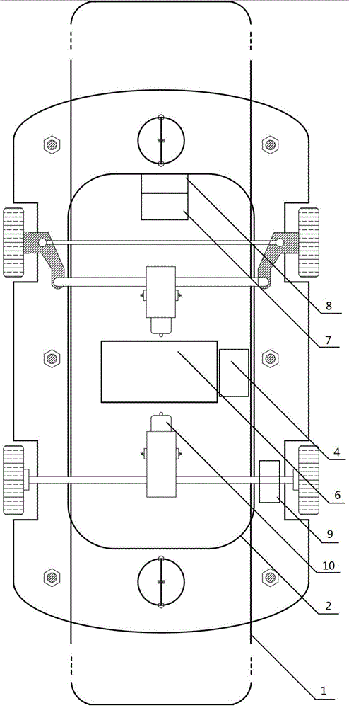
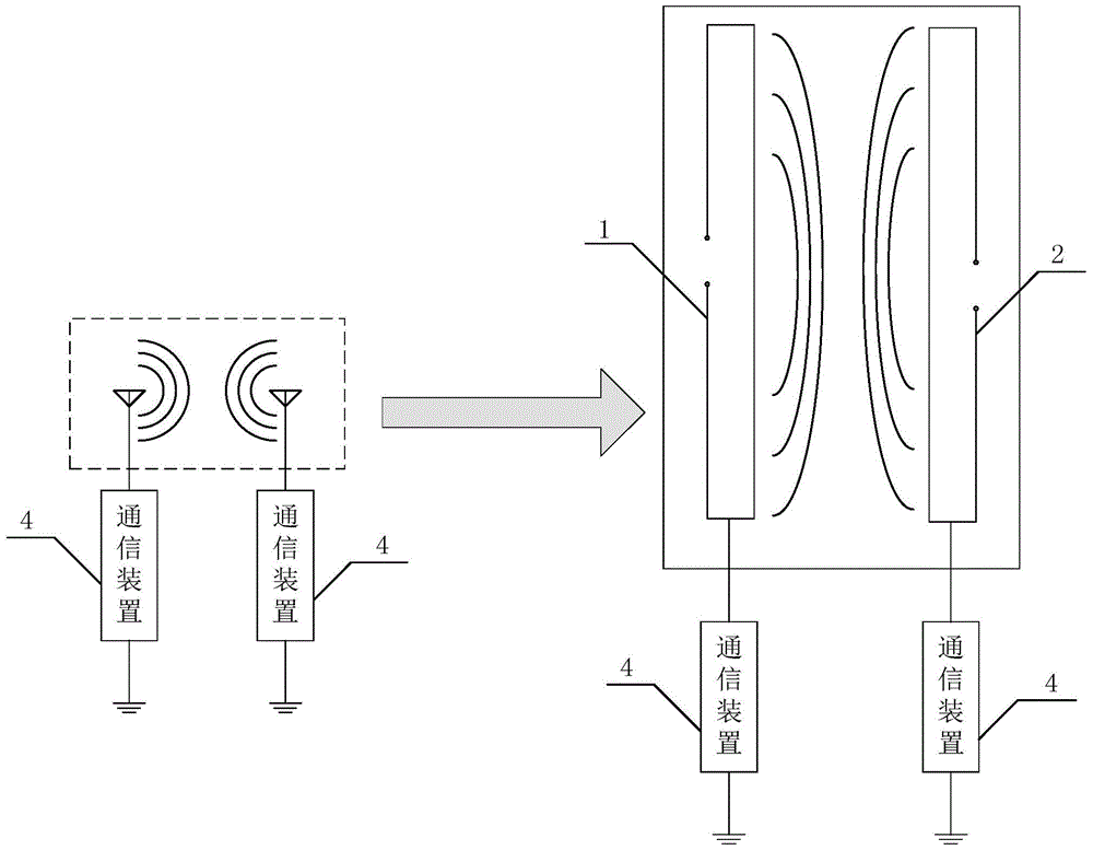
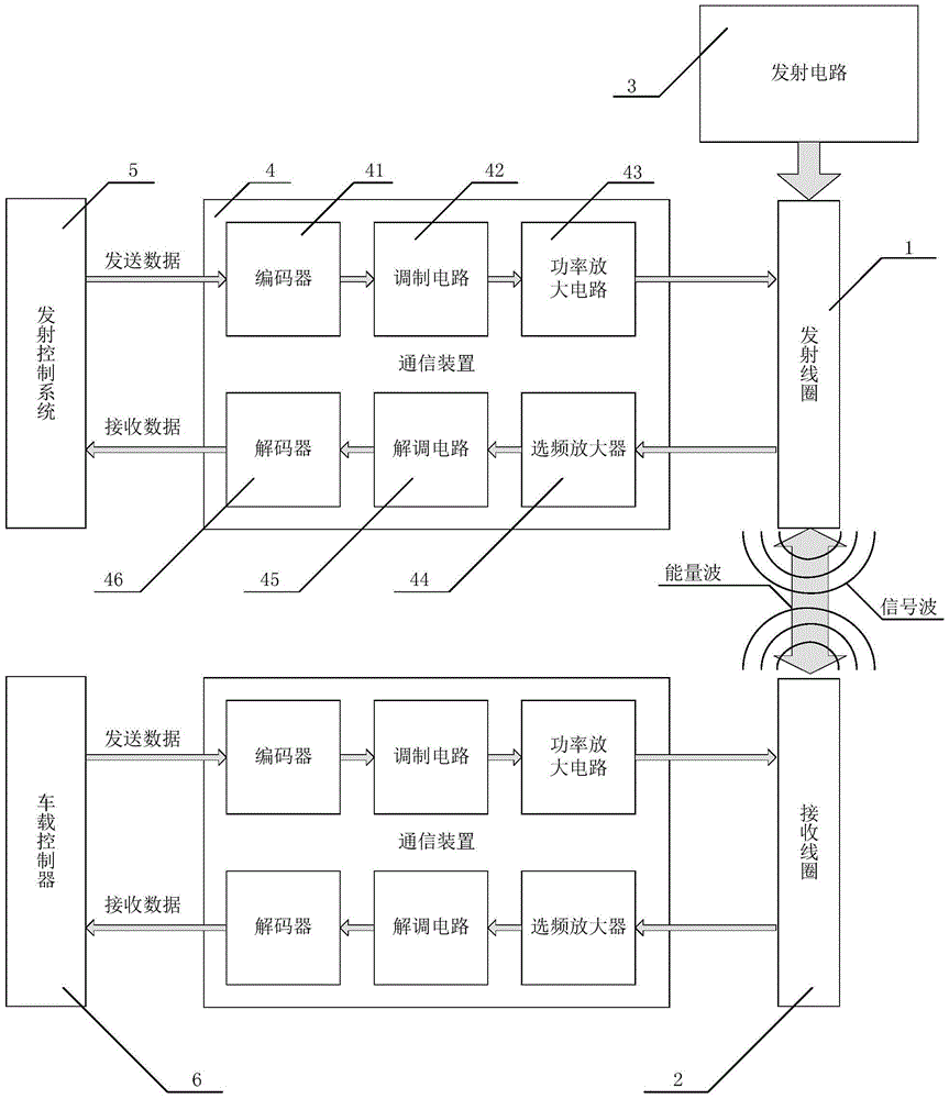
[0031] Such as Figure 1 to Figure 5 As shown, the motion control system of the electromagnetic track type mobile robot of the present invention includes a transmitting coil 1, a receiving coil 2, a transmitting circuit 3, a communication device 4, a transmitting control system 5, an on-board controller 6, an amplitude detector 7, a compensation Capacitor group 8 and speed sensor 9; transmitting coil 1 is laid on the ground, and receiving coil 2 is installed on the mobile robot. Data transmission is performed between the system 5 and the on-board controller 6 through the communication device 4 , the transmitting coil 1 , and the receiving coil 2 . The on-board controller 6 sends the speed signal collected from the speed sensor 9 to the communication device 4, and through the communication between the transmitting coil 1 and the recei...


PUM


Abstract

The invention relates to a motion control system for electromagnetic track type mobile robots and a control method. A transmitting coil and a receiving coil in the system are formed into an energy transmission channel and multiplexed as an antenna of a communication device to form a communication system, an on-board controller transmits a speed signal acquired by a speed sensor to a transmission control system, the transmission control system compares current speed with given speed, a PID (Proportion Integration Differentiation) algorithm is utilized to control the power of the transmission circuit after an error is obtained, and the rotational speed of a driving motor is controlled by the transmission circuit; an amplitude detector and a compensating capacitor bank are formed into a self-adaptive resonant frequency control system, the amplitude detector detects the current amplitude of the resonant voltage of the receiving coil, converts the acquired amplitude into a digital value and transmits the digital value to the on-board controller, and the on-board controller connects or disconnects more than one low-capacity capacitor in the compensating capacitor bank with or from a circuit. The method is based on the control system. The system has the advantages of simple and compact structure, convenience in operation, high control precision, high communication quality, high reliability and the like.

Description

technical field [0001] The invention mainly relates to the control field of mobile robots, in particular to a motion control method of an electromagnetic rail type mobile robot. Background technique [0002] At present, in the field of application of mobile robots, electromagnetic orbital mobile robots have begun to appear in people's field of vision. This type of robot generally moves along a predetermined trajectory, and its energy is mainly provided by the transmitting coil laid under the ground. Among them, the magnetic coupling resonance system is composed of the transmitting coil under the ground and the receiving coil fixed on the mobile robot body. The high-frequency alternating current generated on the receiving coil is processed by the on-board controller to supply power to the mobile robot. The motion control of this type of robot is not yet However, the application potential of this type of robot cannot be fully explored, and there are still a series of problems ...

Claims


Application Information

Patent Timeline
Patent Type & Authority Patents(China)
IPC IPC(8): G05D1/02
Inventor 樊绍胜李森涛李富林卫星沈春阳
Owner CHANGSHA UNIVERSITY OF SCIENCE AND TECHNOLOGY
Learn More