
Centrally-managed touch electricity-saving switch controlling system

A switch control system and centralized management technology, which is applied in general control systems, control/regulation systems, program control, etc., can solve the problems of mechanical switches with large noise, severe mechanical wear, and easy ignition of sparks, etc., to eliminate control blind spots , saving resources and simplifying wiring

Inactive Publication Date: 2014-04-02
JIANGMEN LIANCHUANG DEV
View PDF7 Cites 1 Cited by
  • Summary
  • Abstract
  • Description
  • Claims
  • Application Information

AI Technical Summary

Problems solved by technology

[0003] (1) The mechanical switch has high noise, severe mechanical wear, and is easy to be damaged; and the switch adopts a strong current direct on-off switch, which is easy to generate sparks and has certain safety hazards
[0004] (2) Each control unit of the mechanical switch must be controlled by one line and one switch, which virtually increases the wiring cost and wire loss
[0005] (3) Mechanical switches take up a lot of space, have high wiring costs, and are not easy to achieve centralized management; let alone flexible control
[0006] Due to the above-mentioned inconvenient control, there are many control blind spots in the home, office and other places, and even many electrical appliances are in the standby working state all the year round.

Method used


Image

  • Centrally-managed touch electricity-saving switch controlling system
  • Centrally-managed touch electricity-saving switch controlling system
  • Centrally-managed touch electricity-saving switch controlling system

Examples


Embodiment Construction

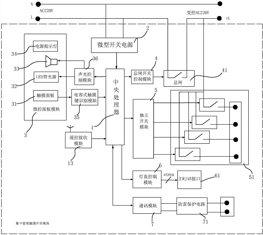
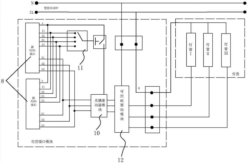
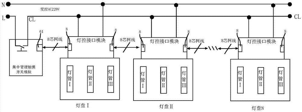
[0043] refer to Figure 1 to Figure 3 , a centralized management touch power-saving switch control system of the present invention mainly includes two parts: a centralized management touch switch module and a light control interface module installed on the lamp panel.

[0044] The centralized management touch switch module includes a central processing unit 1, a micro-control panel module 3, a main gate 41 and a main gate switch control module 4, a relay array 51 and an independent switch control module 5, a lamp panel control module 6, a communication module 7, Remote control receiving module 13 and micro switch power supply 2.

[0045] The central processing unit 1 is the thinking core of the system, and it is connected with the micro-control panel module 3, the main switch control module 4, the independent switch control module 5, the lamp panel control module 6, the communication module 7, the remote control receiving module 13 and the micro switch The power supply 2 is c...


PUM


Abstract

The invention discloses a centrally-managed touch electricity-saving switch controlling system. A centrally-managed touch electricity-saving switch mainly comprises two parts, i.e. a centrally-managed touch-switch module and a lamp-controlling interface module, wherein the lamp-controlling interface module is installed on a lamp panel. A microcomputer controlling technology is adopted by the touch electricity-saving switch, the central management for many kinds of switches can be realized through a touch panel, the touch electricity-saving switch is integrated with an independent switch module for controlling electricity-using equipment, such as televisions, sounders, computers and table lamps, a zone-bit-dividing and brightness-dividing flexible control mode is implemented for an illuminating system, and the touch electricity-saving switch has one-key turn-off and electricity-saving functions. According to the centrally-managed touch electricity-saving switch controlling system, the purposes of simplifying wiring, saving resources and clearing away a blind control area are achieved by means of controlling strong current by weak current, controlling an interface in a standardized way and the like, and finally the purpose of electricity saving is achieved. The centrally-managed touch electricity-saving switch controlling system is also provided with a remote-control receiving module and a communication module, so that mobile control and mobile-phone or network remote monitoring can be realized, and the centrally-managed touch electricity-saving switch controlling system is especially suitable for controlling lamplight, sockets and the like at places, such as families and workplaces.

Description

technical field [0001] The invention relates to a centralized management touch power-saving switch control system. Background technique [0002] The power switch is a product that we use every day in our daily life. At present, the conventional mechanical switches have the following defects. [0003] (1) The mechanical switch has high noise, severe mechanical wear, and is easy to be damaged; and the switch adopts a strong current direct on-off switch, which is easy to generate sparks and has certain safety hazards. [0004] (2) Each control unit of the mechanical switch must be controlled by one switch per line, which virtually increases the wiring cost and wire loss. [0005] (3) Mechanical switches take up a lot of space, have high wiring costs, and are not easy to achieve centralized management; let alone flexible control. [0006] Due to the inconvenience of the above-mentioned various controls, there are many control blind spots in places such as homes and offices, a...

Claims


Application Information

Patent Timeline
IPC IPC(8): G05B19/042G08C17/00
Inventor 胡志军
Owner JIANGMEN LIANCHUANG DEV
Learn More