
Continuous feeding device and process of cement kiln cooperation urban garbage system

A technology for co-processing, municipal waste, applied in combustion methods, combustion types, incinerators, etc.

Inactive Publication Date: 2014-04-02
CITIC HEAVY INDUSTRIES CO LTD
View PDF13 Cites 1 Cited by
  • Summary
  • Abstract
  • Description
  • Claims
  • Application Information

AI Technical Summary

Problems solved by technology

Garbage accumulates on the valve plate when the flapper valve is closed, and enters the L-shaped incinerator when the flapper valve is opened. This intermittent feeding method makes the materials entering the incinerator intermittent, resulting in the filling of the incinerator. The rate fluctuates from high to low, the combustion temperature fluctuates from high to low, and the combustion temperature is difficult to control
[0006]2. The materials entering the incinerator cannot be measured
[0007] 3. Poor sealing: due to the negative pressure environment in the incinerator, when the flapper valve is opened, a large amount of cold air will be sucked into the incinerator, which reduces the air pressure in the incinerator. Combustion temperature, not conducive to garbage combustion
[0008] 4. Poor safety: due to discontinuous feeding, the combustion temperature and combustion environment in the incinerator will fluctuate violently, resulting in frequent occurrence of positive pressure
When there is a positive pressure, with the opening of the feed gate valve, the high-temperature flue gas in the incinerator will spray out from the feed port of the incinerator to ignite the feeding belt, endangering the safety of equipment and personnel
[0009]5. Great impact on the working conditions of the incinerator: discontinuous feeding has a great impact on the working conditions of the incinerator, causing temperature fluctuations in the furnace, which is not conducive to subsequent processes continuous and stable production

Method used


Image

  • Continuous feeding device and process of cement kiln cooperation urban garbage system

Examples


Embodiment Construction

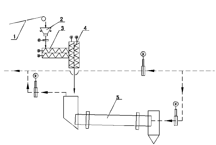
[0025] As shown in the figure: the continuous feeding device of the cement kiln cooperative processing urban waste system is used to transport materials to the L-shaped garbage incinerator 5. The feeding system includes a belt conveyor 1, and the upper part of the belt conveyor 1 The material end is set at the output section of the garbage pretreatment system, and the feeding system also includes a steady flow bin 2, a horizontal screw conveyor 3 and a vertical screw conveyor 4, and the steady flow bin 2 is set on the belt conveyor 1 for feeding Below the end, the discharge port of the steady flow bin 2 is connected to the feed port of the horizontal screw conveyor 3, the vertical screw conveyor 4 is set at the tail end of the horizontal screw conveyor 3, and the outlet of the horizontal screw conveyor 3 The feed port is communicated with the feed port of the vertical screw conveyor 4, and the discharge port of the vertical screw conveyor 4 is connected to the feed port of the ...


PUM


Abstract

The invention relates to a continuous feeding device and process of a cement kiln cooperation urban garbage system. The continuous feeding device comprises a belt conveying machine, a flow stabilizing bin, a horizontal type spiral conveyor and a vertical type spiral conveyor, wherein the flow stabilizing bin is arranged under the discharging end of the belt conveyor; a blanking port of the flow stabilizing bin is connected with a feeding port of the horizontal type spiral conveyor; the vertical type spiral conveyor is arranged at the tail end of the horizontal type spiral conveyor; a discharging port of the horizontal type spiral conveyor is communicated with a feeding port of the vertical type spiral conveyor; a discharging port of the vertical type spiral conveyor is connected with a charging port of an L-shaped garbage incinerator by a chute. The feeding technology adopts a continuous forced feeding mode and can not cause violent fluctuation of the burning temperature and the burning environment in the garbage incinerator, so that positive pressure can be effectively prevented from occurring at a feeding port of the incinerator, and further the condition that when a feeding gate valve is opened, high-temperature flue in the incinerator is ejected from the feeding port of the incinerator to ignite a feeding belt and endanger the safety of persons can be avoided.

Description

technical field [0001] The invention relates to the technical field of material storage and transportation operations, in particular to a continuous feeding device and process for a cement kiln cooperative processing urban waste system. Background technique [0002] The disposal of urban garbage has become a problem of concern all over the world, and it has become a major research topic of environmental protection in today's world. At present, landfill and incineration are the main methods of waste disposal. These two disposal technologies have great disadvantages. The landfill method occupies a large amount of valuable land resources, and the hazard remains for a long time; many domestic waste treatment plants are overloaded, and it is becoming more and more difficult to select a new landfill site. The crisis is likely to spread to more cities. Incineration for power generation will produce fly ash and dioxin and other toxic and harmful gases, causing secondary pollution....

Claims


Application Information

Patent Timeline
Patent Type & Authority Applications(China)
IPC IPC(8): F23G5/033
Inventor 何汪海张平代伟林范东燕周志华许艳丽魏永杰石磊
Owner CITIC HEAVY INDUSTRIES CO LTD
Learn More