Disc and valve stem positioning structure

A positioning structure and butterfly plate technology, which is applied in the direction of lifting valves, valve devices, mechanical equipment, etc., can solve the problems of limited operating space of the structure, affecting positioning accuracy and positioning accuracy, and difficult replacement.

Inactive Publication Date: 2014-04-02
TIANJIN XIANGJIA FLUID CONTROL SYST CO LTD
View PDF7 Cites 0 Cited by
  • Summary
  • Abstract
  • Description
  • Claims
  • Application Information

AI Technical Summary

Problems solved by technology

In this way, it is more difficult to implement in the case of complex structure or limited operating space
In addition, this positioning method is prone to the problem that the movemen...

Method used


Image

  • Disc and valve stem positioning structure
  • Disc and valve stem positioning structure

Examples


Embodiment Construction

[0013] In order to further understand the invention content, characteristics and effects of the present invention, the following examples are given, and detailed descriptions are as follows in conjunction with the accompanying drawings:

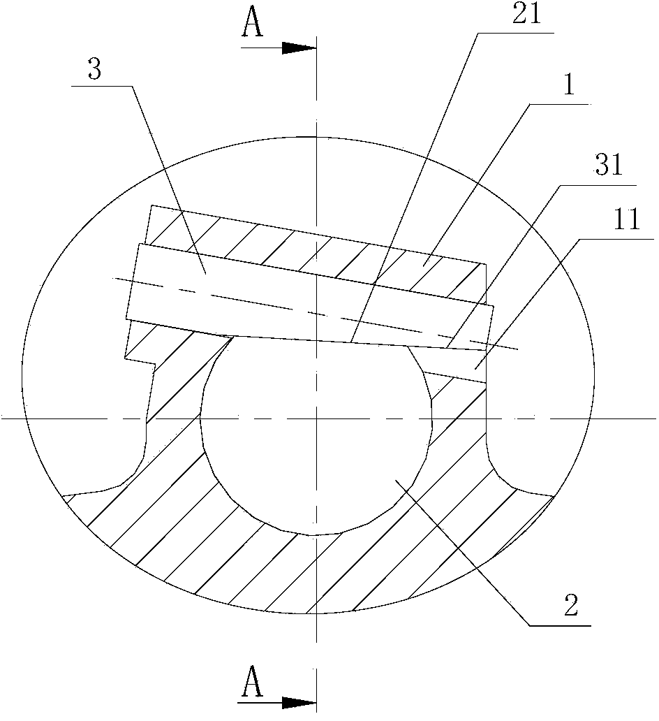
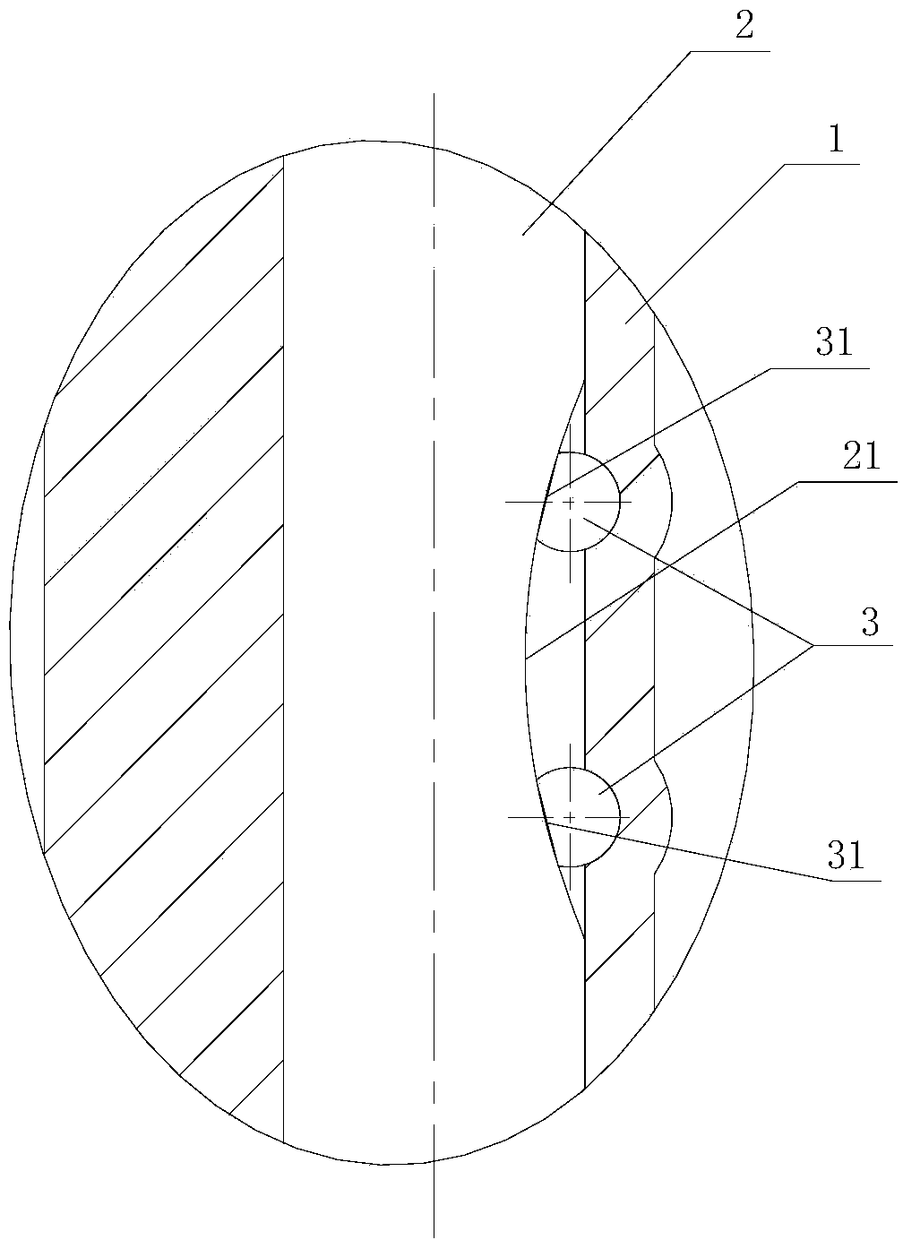
[0014] see figure 1 with 2 , a positioning structure for a butterfly plate and a valve stem, comprising a butterfly plate 1 provided with a mounting hole, a valve stem 2 plugged and connected to the butterfly plate through the mounting hole, and a positioning pin 3 for realizing the axial positioning of the butterfly plate and the valve stem. A pin hole 11 is provided on the butterfly plate, and the pin hole is arranged at the edge of one side of the mounting hole of the butterfly plate. Specifically, the pin hole is composed of a part located in the mounting hole and another part recessed into the wall of the mounting hole, that is, the pin hole is offset relative to the mounting hole on the butterfly plate. A wedge surface A31 is provided...


PUM


Abstract

A disc and valve stem positioning structure comprises a disc, a valve stem, and positioning pins, wherein the valve stem is in inserted connection with the disc and the disc and the valve stem are axially positioned through the positioning pins. The disc is provided with pinholes. The disc and valve stem positioning structure is characterized in that the pinholes are arranged at one edge of a disc mounting hole, the outside of each positioning pin is provided with a wedge surface A which is a flat wedge surface, the corresponding part of the outside of the valve stem is provided with a wedge surface B, and the wedge surface B is an arc wedge surface axially arranged along the valve stem. The positioning structure is available for wedge positioning; through the application of the positioning structure, fitting faces of parts are machined in advance, so that drilling the pinholes during assembly is not required; the positioning structure is especially applicable to conditions with complex structures and difficulty in drilling and even failure of drilling; the radial size of the positioning pins is adjustable, so that positioning is accurate and highly precise; through wedge positioning, the positioning precision can be guaranteed even after multiple mounting and demounting; in addition, the positioning structure has the advantages that mounting and demounting are convenient, a valve connector is easy to replace after being damaged and maintenance cost is low.

Description

technical field [0001] The invention relates to a butterfly valve, in particular to a positioning structure for a butterfly plate and a valve stem. Background technique [0002] At present, the positioning structure of the butterfly plate and the valve stem of the butterfly valve usually adopts a cylindrical pin or a conical pin. Regardless of whether a cylindrical pin or a conical pin is used, the commonly used processing method is to match the drill. In this way, it is more difficult to implement in the case of complex structure or limited operating space. In addition, this positioning method is prone to the problem that the movement gap affects the positioning accuracy and positioning accuracy. In addition, if the butterfly plate or valve stem is damaged, this positioning method is not easy to replace the damaged parts. Contents of the invention [0003] In order to solve the technical problems existing in the known technology, the present invention provides a valve w...

Claims


Application Information

Patent Timeline
IPC IPC(8): F16K1/22F16K1/32B23P19/04B23P19/10
CPCF16K1/22F16K1/487
Inventor 李华雷金成波代艳东潘晓琳
Owner TIANJIN XIANGJIA FLUID CONTROL SYST CO LTD
Why Eureka
Try Eureka