
Control device for industrial sewing machines

An industrial sewing machine and control device technology, which is applied to sewing machine control devices, sewing machine components, sewing equipment, etc., can solve the problem of incompatible control of pneumatic solenoid valves and electric solenoids, and achieve switching efficiency, cost saving, and production convenience. Effect

Active Publication Date: 2015-07-01
ZHEJIANG ZOBOW MECHANICAL & ELECTRICAL TECH
View PDF5 Cites 0 Cited by
  • Summary
  • Abstract
  • Description
  • Claims
  • Application Information

AI Technical Summary

Problems solved by technology

[0005] In view of the shortcomings of the prior art described above, the purpose of the present invention is to provide a control device for an industrial sewing machine, which is used to solve the problem of incompatible control between the pneumatic solenoid valve and the electric electromagnet in the existing industrial sewing machine

Method used


Image

  • Control device for industrial sewing machines
  • Control device for industrial sewing machines

Examples


Embodiment Construction

[0043] Embodiments of the present invention are described below through specific examples, and those skilled in the art can easily understand other advantages and effects of the present invention from the content disclosed in this specification. The present invention can also be implemented or applied through other different specific implementation modes, and various modifications or changes can be made to the details in this specification based on different viewpoints and applications without departing from the spirit of the present invention. It should be noted that, in the case of no conflict, the following embodiments and features in the embodiments can be combined with each other.

[0044] It should be noted that the diagrams provided in the following embodiments are only schematically illustrating the basic ideas of the present invention, and only the components related to the present invention are shown in the diagrams rather than the number, shape and shape of the compo...


PUM


Abstract

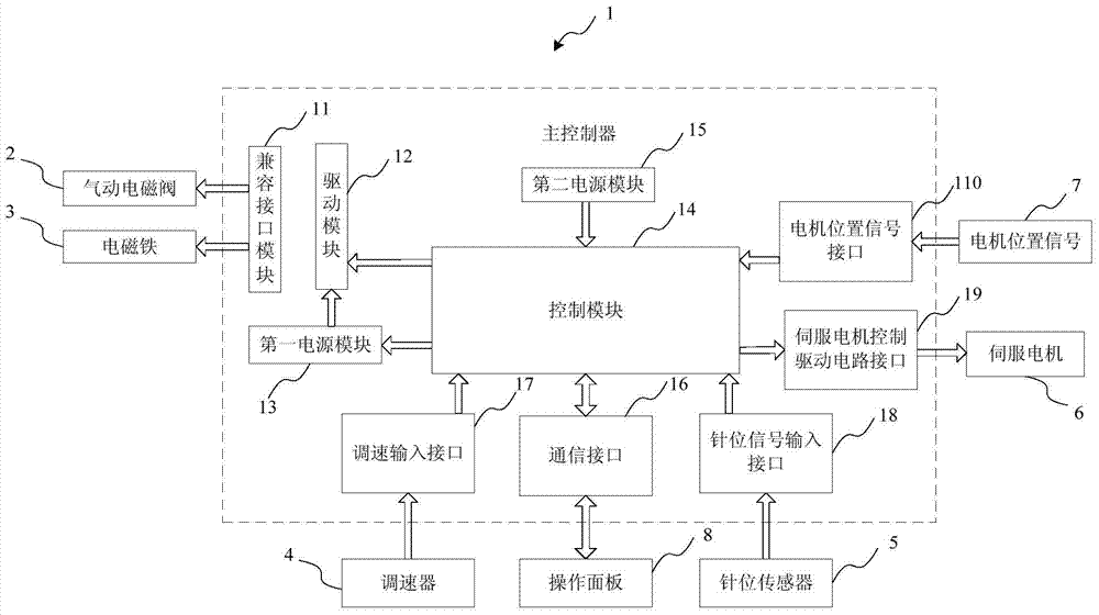
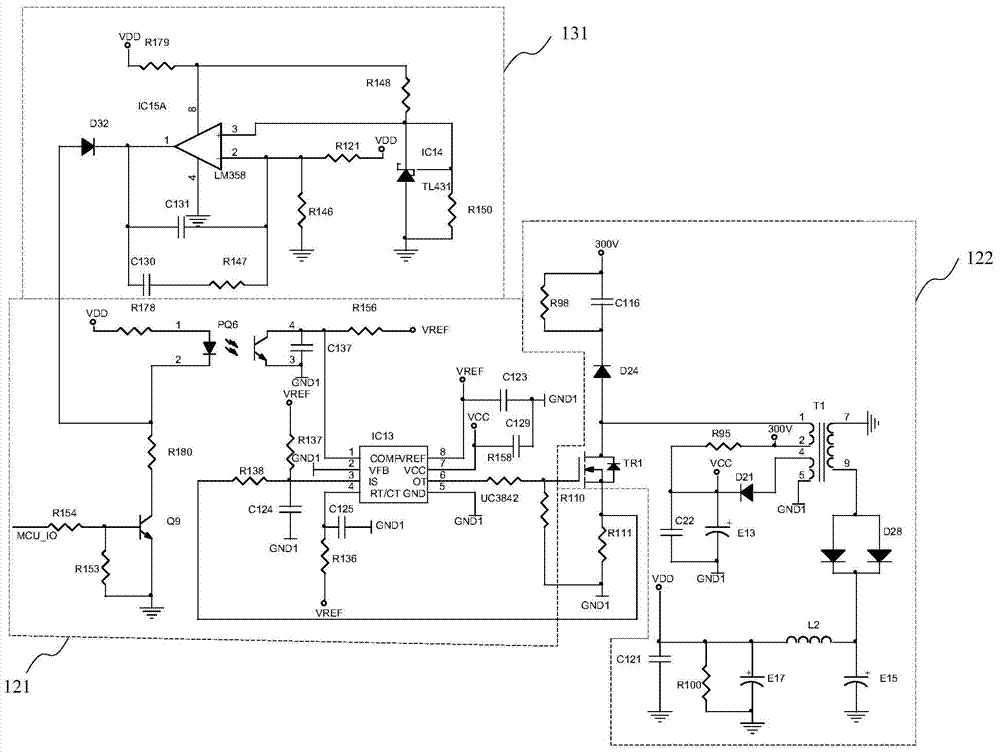
The invention provides a control device for industrial sewing machines. The control device comprises a compatible interface module, a drive module, a first power module, a control module, a second power module, and a peripheral interface. The compatible interface module is used for providing an interface which can be connected with both a pneumatic electromagnetic valve and an electromagnet. The drive module generates different drive voltages to drive the pneumatic electromagnetic valve and the electromagnet according to different control signals. The first power module is used for providing the drive module with operating power and controlling and regulating the operating power. The control module is used for outputting different control signals to the drive module. The second power module is used for providing the control module with operating power. The peripheral interface is used for connecting the control module and a peripheral device. The control module is connected with an operating panel through a communication interface. The operating panel is operated to drive the control module to generate the different control signals. Through the application of the control device, the problem that the pneumatic electromagnetic valve and the electric electromagnet in the existing industrial sewing machines cannot be compatibly controlled is effectively solved.

Description

technical field [0001] The invention relates to the field of sewing machines, in particular to a control device for an industrial sewing machine compatible with a pneumatic solenoid valve / electric solenoid. Background technique [0002] Industrial sewing machines are widely used machines with many specifications. With the continuous development of mechatronics technology, more and more functions are realized by industrial sewing machines. Many industrial sewing machines require various machine head actions during the application process, such as thread trimming, presser foot lifting, etc. Such machine head actions are generally realized through pneumatic solenoid valves or electromagnets. [0003] However, usually due to the difference in working voltage and working mode between the pneumatic solenoid valve and the electromagnet, the existing electronic control system can only support one of them, that is, either the pneumatic solenoid valve or the electromagnet is suitable...

Claims


Application Information

Patent Timeline
Patent Type & Authority Patents(China)
IPC IPC(8): D05B69/00
Inventor 甘海春李丽朱良华
Owner ZHEJIANG ZOBOW MECHANICAL & ELECTRICAL TECH
Learn More