
Automatic filled injection pump system

An automatic filling and syringe pump technology, applied in the direction of pressure infusion, devices introduced into the body, etc., can solve the problems of inaccurate control of contrast agent dilution concentration, high pipeline cost, residual waste, etc., to reduce the probability of adverse reactions and avoid The effect of secondary pollution and avoiding waste

Inactive Publication Date: 2014-04-02
肖进
View PDF0 Cites 3 Cited by
  • Summary
  • Abstract
  • Description
  • Claims
  • Application Information

AI Technical Summary

Problems solved by technology

[0007] In order to overcome the shortcomings of the existing push-injection contrast medium injection pump, which is easy to cause secondary pollution during the filling process and residual waste after injection, the roller extrusion contrast medium injection pump cannot accurately control the dilution concentration of contrast medium, and the cost of the pipeline is high. The present invention designs an automatic filling injection pump system, which has all the advantages of the basic structure of a push-injection contrast medium injection pump and can precisely control the concentration of contrast medium, and at the same time avoids manual filling of contrast medium by adding an automatic filling mechanism. The risk of secondary pollution is caused, and the automatic quantitative filling of contrast medium is controlled by the processor before injection to avoid the waste of residual contrast medium

Method used


Image

  • Automatic filled injection pump system
  • Automatic filled injection pump system
  • Automatic filled injection pump system

Examples


Embodiment Construction

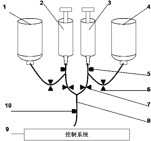
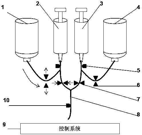
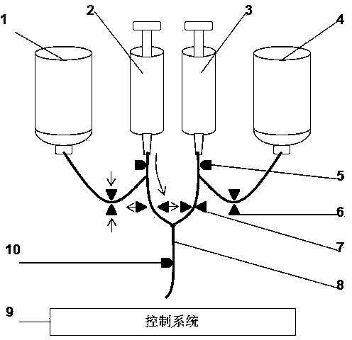
[0022] exist figure 1 In the structural diagram of the implementation example shown, the contrast agent branch and the saline branch are connected through the first Y-shaped interface, and the trunk merged into a Y-shaped trunk in the infusion direction is connected to the patient. The contrast agent injector (2) and the contrast agent container (1) are in fluid communication through the infusion tube (8), where the infusion tube (8) forms a second inverted Y-shaped joint, and the contrast agent injector (2) is connected at the second On the trunk of the first Y-shape, the contrast agent container (1) is connected to a branch of the second Y-shape, and the other branch is partly communicated with the saline pipeline in the direction of infusion. The filling stop valve (6) is located on the branch of the second Y-shaped contrast medium container (1), the filling air sensor (5) is located on the trunk of the second Y line, and the infusion stop valve (7) is located on the secon...


PUM


Abstract

The invention relates to an automatic filled injection pump system. The automatic filled injection pump system is composed of a contrast medium branch and a saline solution branch and comprises a contrast medium injector, a saline solution injector, a contrast medium container, a saline solution container, a filling liquid stopping valve, an infusion liquid stopping valve, a filling bubble sensor, an infusion tube and a control system, wherein the contrast medium branch and the saline solution branch are connected with each other through a first Y-shaped interface and are converged to form a Y-shaped truck connected to a patient in an infusion direction; the contrast medium injector and the contrast medium container are communicated with each other through fluid in the infusion tube, and the infusion tube forms a second inverse Y-shaped connector herein; and the saline solution injector and the saline solution container are communicated with each other through the fluid in the infusion tube, and the infusion tube forms a third inverse Y-shaped connector herein. Compared with an existing product, the automatic filled injection pump system has the advantages of conventional injection-type and idler wheel-type contrast medium injection systems.

Description

technical field [0001] The present invention relates to computed tomography (CT) and magnetic resonance imaging (MRI), especially to a syringe pump for injecting contrast media. Background technique [0002] CT and MRI scans rely on intravenous contrast agents to improve image quality and improve diagnostic accuracy. From the perspective of the syringe pump, there is not much difference between CT and MRI contrast injections, but the syringe pump used in the MRI environment needs to be able to withstand the interference of the magnetic field strength of 1T, and cannot interfere with the magnetic field of MRI. Syringe pumps for MRI typically use batteries or a DC power supply to minimize the effect of the magnetic field. [0003] There are two main types of contrast medium injection pumps on the market. One is bolus, such as medrad Vistron CT for CT, medrad EnVision CT, medrad Stellant CT, medtron Injektron CT2, medtron Injektron 82CT, medtron Injektron 82 HP, medtron Accut...

Claims


Application Information

Patent Timeline
IPC IPC(8): A61M5/142
Inventor 肖进
Owner 肖进
Learn More