
Communication device

A communication device and antenna technology, which is applied in the direction of antenna support/installation device, radiating element structure, electrical components, etc., can solve the problems of large internal space, inflexible placement of traditional antennas, and large antenna volume, etc., to achieve the installation position flexible effects

Inactive Publication Date: 2014-03-26
AMBIT MICROSYSTEMS (SHANGHAI) LTD +1
View PDF5 Cites 8 Cited by
  • Summary
  • Abstract
  • Description
  • Claims
  • Application Information

AI Technical Summary

Problems solved by technology

Due to the large volume of this antenna, it takes up a large internal space of the communication device, so the traditional communication device is relatively thick
At the same time, due to the limitation of internal space and structure, the placement of traditional antennas is not flexible enough

Method used


Image

  • Communication device
  • Communication device
  • Communication device

Examples


Embodiment Construction

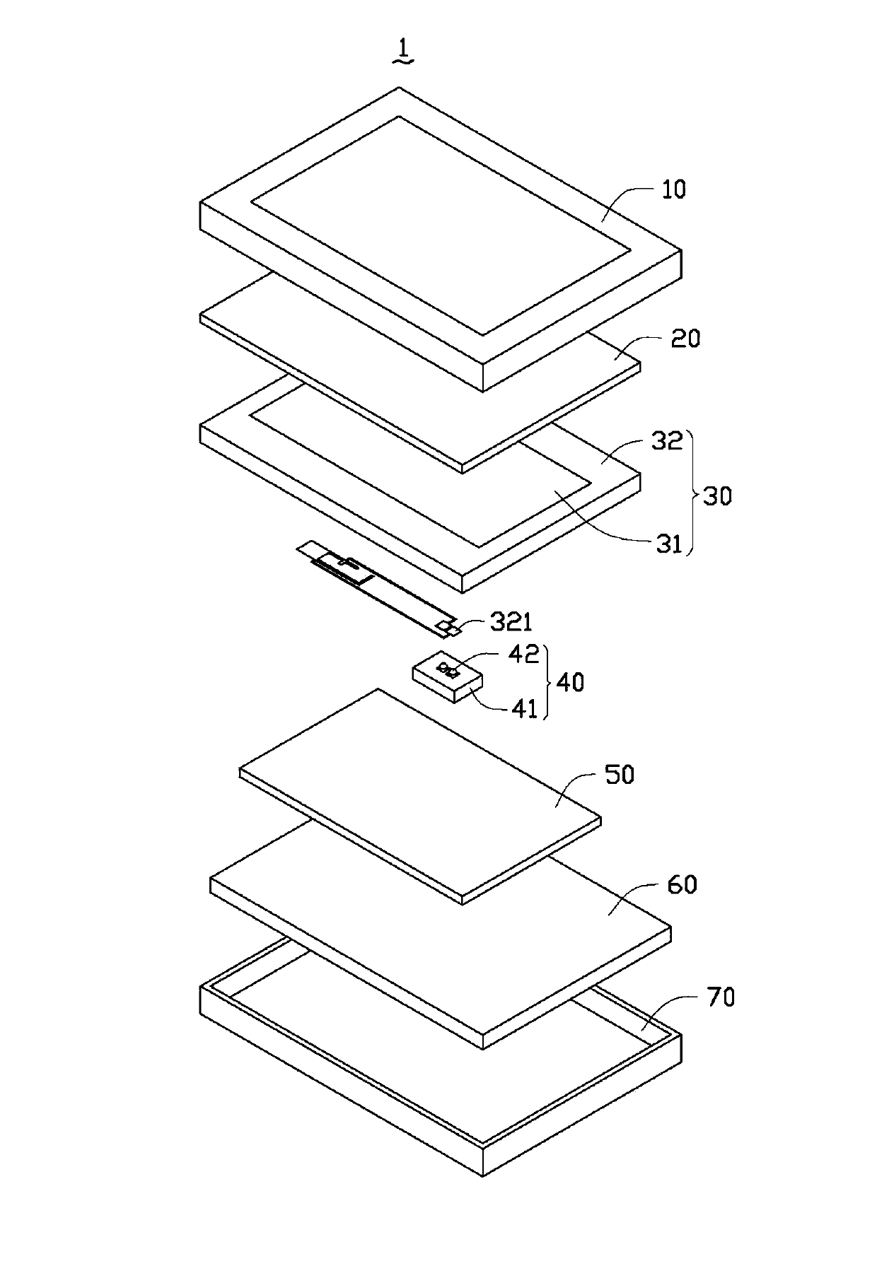
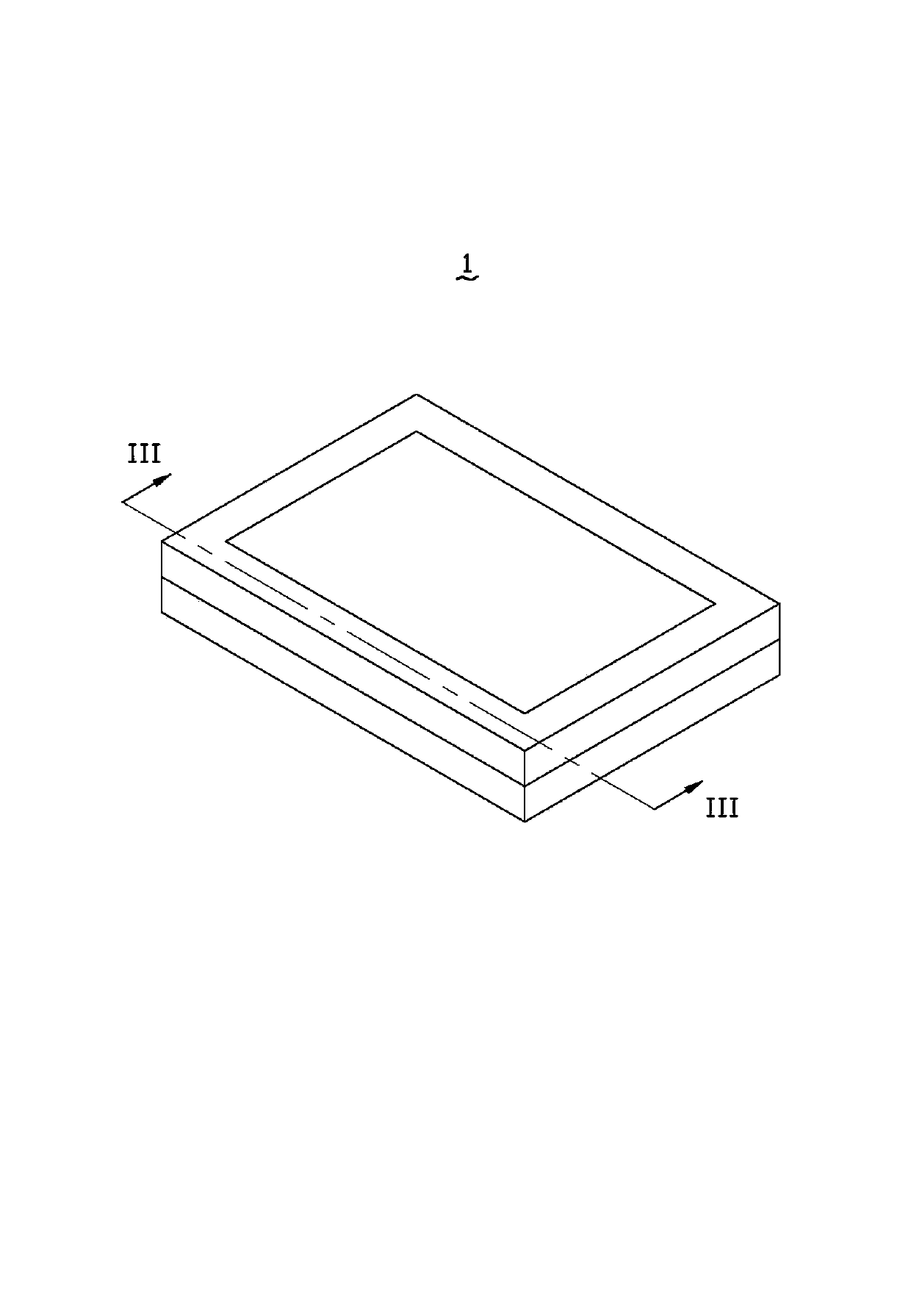
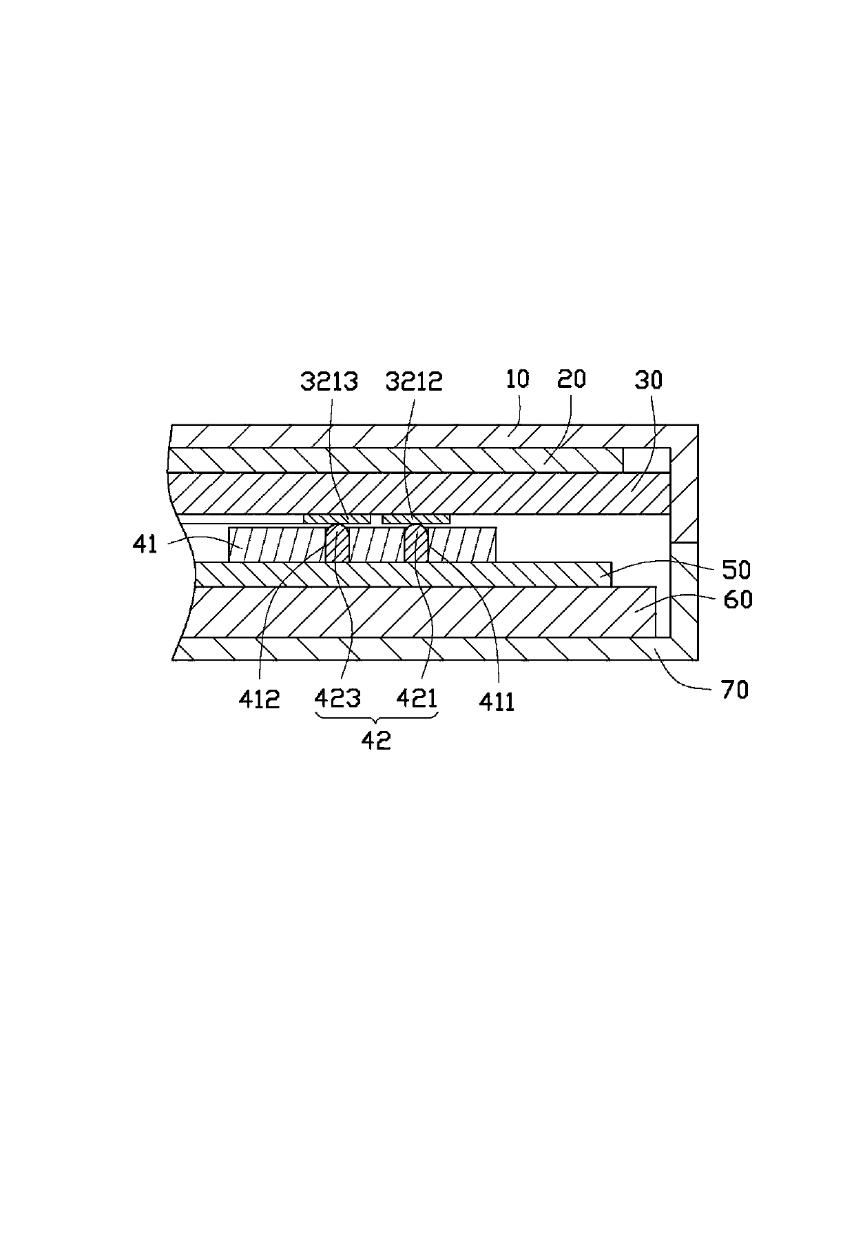
[0013] Please also refer to figure 1 , figure 2 with image 3 , figure 1 It is a three-dimensional schematic diagram of a preferred embodiment of the communication device of the present invention. figure 2 yes figure 1 The three-dimensional assembly diagram of the communication device shown. image 3 yes figure 2 The communication device shown is a cross-sectional view along the line III-III. The communication device 1 includes a first frame 10 , a protective glass 20 , a touch panel 30 , a connecting device 40 , a circuit board 50 , a battery 60 and a second frame 70 . The first frame 10 and the second frame 70 form a receiving space for receiving the cover glass 20 , the touch panel 30 , the connecting device 40 , the circuit board 50 and the battery 60 . The battery 60 , the circuit board 50 , the connecting device 40 , the touch panel 30 and the cover glass 20 are sequentially disposed on the second frame 70 .

[0014] The protective glass 20 is used to protect ...


PUM


Abstract

The invention relates to a communication device. The communication device comprises a touch control panel and a circuit board. The touch control panel comprises a touch area and a non-touch area. The touch area is used for receiving a touch control operation of a user to generate a corresponding touch control signal. The non-touch area extends outward from the edge of the touch control area and is provided with a plurality of touch control electrodes. The circuit board is electrically connected with the touch control electrodes of the touch control panel and is used for driving the communication device to work. The communication device further comprises an antenna which is arranged on the non-touch area through a printing process and is electrically connected with the circuit board.

Description

technical field [0001] The present invention relates to a communication device. Background technique [0002] Antenna is a part of wireless communication products that uses electromagnetic conversion to receive and transmit signals. A traditional antenna is formed by winding an induction coil such as an enameled wire and encapsulating it with an insulating film. At present, traditional communication devices usually use double-sided tape to paste the traditional antenna inside the casing, and then connect it to the circuit board through wires. Since such an antenna has a large volume, it occupies a relatively large internal space of the communication device, so the traditional communication device is relatively thick. At the same time, due to the limitations of internal space and structure, the placement of traditional antennas is not flexible enough. Contents of the invention [0003] In view of the above problems, it is necessary to provide an effectively thinner commu...

Claims


Application Information

Patent Timeline
Patent Type & Authority Applications(China)
IPC IPC(8): H01Q1/22H01Q1/38
CPCH01Q1/243
Inventor 杨贵敏侯宗坤
Owner AMBIT MICROSYSTEMS (SHANGHAI) LTD
Learn More