A method for forming pmos source and drain

A technology of source-drain and epitaxial growth, which is applied in the direction of electrical components, semiconductor/solid-state device manufacturing, semiconductor devices, etc., and can solve problems such as device performance degradation

Active Publication Date: 2016-06-01
SEMICON MFG INT (SHANGHAI) CORP
View PDF5 Cites 0 Cited by
  • Summary
  • Abstract
  • Description
  • Claims
  • Application Information

AI Technical Summary

Problems solved by technology

[0003] In order to obtain better performance, in the process of preparing PMOS, epitaxial SiGe is usually carried out in the source and drain regions of PMOS to apply compressive stress to the channel of the substrate, and then ion implantation is performed after epitaxial SiGe to obtain a higher doping concentration. In this process, high-energy, low-dose B (Boron) is usually used to dope the source and drain to form a doping tail (dopingtail) profile to reduce the leakage at the junction, but in the source of PMOS SiGe Ion implantation usually leads to strain relaxation of the device after annealing, and the strain relaxation will directly lead to the degradation of device performance.
[0004] Therefore, in order to reduce the source-drain relaxation caused by ion implantation, the source-drain implantation step should be skipped as much as possible, but the control of the pattern at the junction becomes a challenge, and it is necessary to improve the current source-drain implantation method in PMOS to solve the current problem. There are various problems in the technology

Method used


Image

  • A method for forming pmos source and drain
  • A method for forming pmos source and drain

Examples


Embodiment Construction

[0030] In the following description, numerous specific details are given in order to provide a more thorough understanding of the present invention. It will be apparent, however, to one skilled in the art that the present invention may be practiced without one or more of these details. In other examples, some technical features known in the art are not described in order to avoid confusion with the present invention.

[0031] In order to thoroughly understand the present invention, a detailed description will be provided in the following description to illustrate the method for forming the PMOS source and drain of the present invention. Obviously, the practice of the invention is not limited to specific details familiar to those skilled in the semiconductor arts. Preferred embodiments of the present invention are described in detail below, however, the present invention may have other embodiments besides these detailed descriptions.

[0032] It should be noted that the terms...


PUM


Abstract

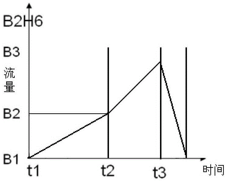
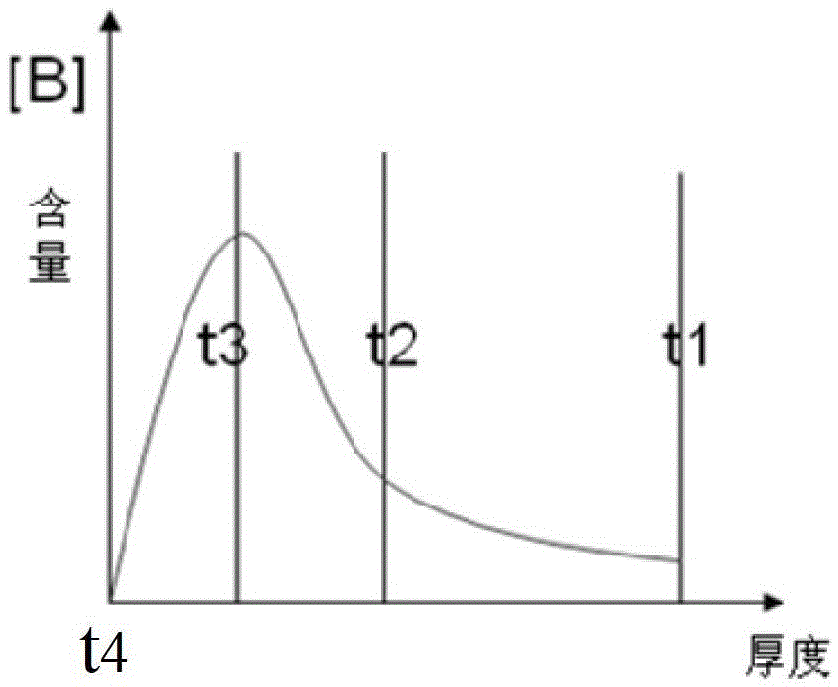
The invention relates to a PMOS source and drain formation method which includes: a semiconductor substrate which at least includes a gate structure is provided; and grooves are formed at the two sides of a gate and epitaxial growth of SiGeB layers is performed in the grooves. The method is characterized in that during epitaxial growth of SiGe, B is doped at an original position at the same time so as to facilitate epitaxial growth of the SiGeB layers in the grooves. The method includes the following steps specifically: 1) inletting B2H6 gas and controlling gas flow to increase from B1 to B2 and time to be T1; 2) increasing the gas flow of B2H6 from B2 to B3 and time to be T2; 3) adjusting the flow of B2H6 gas to drop from B3 to 0 and time to be T3, wherein T2 is > T3; and the SiGeB layers are the B-doped source and drain of in a PMOS. The method is capable of skipping a separated ion injection process so that stress in a channel region can be maintained and thus a device obtained through manufacturing is better in performance.

Description

technical field [0001] The invention relates to the field of semiconductors, and in particular, the invention relates to a method for forming a PMOS source and drain. Background technique [0002] With the continuous development of semiconductor technology, the preparation of semiconductor devices tends to be miniaturized, and has been developed to the nanometer level, while the preparation process of conventional devices is gradually mature. The current method of preparing PMOS often includes the following conventional steps: firstly, a semiconductor substrate is provided, and then double wells, shallow trench isolation and polysilicon gate structures are formed on the semiconductor substrate. As the width of the gate continues to decrease, the gate The channel length under the structure is also continuously reduced. In order to effectively prevent the short channel effect, a lightly doped drain process (LDD) is introduced in the integrated circuit manufacturing process, an...

Claims


Application Information

Patent Timeline
Patent Type & Authority Patents(China)
IPC IPC(8): H01L21/28
CPCH01L21/2033H01L21/2205H01L29/66477
Inventor 金兰涂火金
Owner SEMICON MFG INT (SHANGHAI) CORP
Why Eureka
Try Eureka