
Built-in converter transformer core pulling plate column ring-current bypass structure

A converter transformer, built-in technology, applied in the direction of transformer/inductor magnetic core, transformer/inductor components, circuits, etc., can solve the problems of magnetic flux leakage, overheating, increase in pull-board resistance loss, etc., to achieve reasonable layout, The effect of reducing pull plate loss and saving space

Inactive Publication Date: 2014-03-26
BAODING TIANWEI BAOBIAN ELECTRICAL
View PDF4 Cites 10 Cited by
  • Summary
  • Abstract
  • Description
  • Claims
  • Application Information

AI Technical Summary

Problems solved by technology

[0002] For high-end large-capacity converter transformers, there is inevitably the same problem, that is, the magnetic flux leakage of the tapped lead wires of the voltage regulating winding will generate an induced current in the core frame, and the strong induced current will cause a sharp loss of the pull plate resistance. increased, causing local overheating

Method used


Image

  • Built-in converter transformer core pulling plate column ring-current bypass structure
  • Built-in converter transformer core pulling plate column ring-current bypass structure

Examples


Embodiment Construction

[0011] Below in conjunction with accompanying drawing, the present invention will be further described by examples.

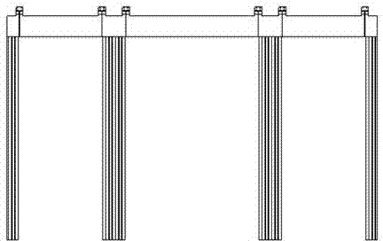
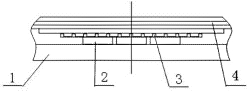
[0012] Refer to attached figure 1 , 2 , 3, a built-in converter transformer core tie plate inter-column circulation bypass structure, including clamp 1, pull plate 2, copper compensation ring 3 and iron core lamination 4, copper compensation ring 3 is arranged on the surface of iron core lamination 4 On the top, the copper compensation ring, the upper and lower clamps and the iron core main column pull plate form a short-circuit ring along the core window, and the copper compensation ring 3 is clamped and fixed by the clamp 1 and the pull plate 2.

[0013] The output current of the voltage regulating coil of the converter transformer can reach up to tens of thousands of amperes. In order to avoid the current passing through the side yoke pull plate with a small cross-section, the side yoke pull plate is disconnected from the upper and lower clamps, and an exte...


PUM


Abstract

The invention relates to a built-in converter transformer core pulling plate column ring-current bypass structure, in particular to a large-capacity converter transformer core pulling plate column ring-current bypass structure, and belongs to the technical field of transformer manufacturing. According to the technical scheme, the structure comprises a clamping piece (1), a pull plate (2), a copper compensation ring (3) and a core-lamination stack (4), the copper compensation ring (3) is arranged on the surface of the core-lamination stack (4), a short circuit loop is formed along an iron core window, and the copper compensation ring (3) is clamped and fixed to the pull plate (2) through the clamping piece (1). The built-in converter transformer core pulling plate column ring-current bypass structure has the advantages that the energy consumption of the pull plate is reduced on the premise that the structure and strength of the pull plate are not changed, eddy-current loss on iron core last-stage iron is greatly reduced, the space is saved, the structure is simple, and overall arrangement is reasonable.

Description

technical field [0001] The invention relates to a built-in converter transformer iron core tie-plate column circulation bypass structure, in particular to a large-capacity converter transformer iron core tie-plate column circulation bypass structure, which belongs to the technical field of transformer manufacturing. Background technique [0002] For high-end large-capacity converter transformers, there is inevitably the same problem, that is, the magnetic flux leakage of the tapped lead wires of the voltage regulating winding will generate an induced current in the core frame, and the strong induced current will cause a sharp loss of the pull plate resistance. Increased, so that the local overheating. Contents of the invention [0003] The object of the present invention is to provide a built-in converter transformer core pull plate inter-column circulation bypass structure, add copper compensation ring on the surface of the iron core, make the copper compensation ring for...

Claims


Application Information

Patent Timeline
IPC IPC(8): H01F27/26H01F27/245H01F27/34
Inventor 王冰邸晓丹彭广勇孙优良王海磊赵文祥王清璞
Owner BAODING TIANWEI BAOBIAN ELECTRICAL
Learn More