
Color decomposing compound prism

A prism and anti-reflection film technology, applied in prisms, instruments, coatings, etc., can solve the problems of temperature rise of reflective display elements and damage of reflective display elements.

Active Publication Date: 2014-03-26
KONICA MINOLTA INC
View PDF7 Cites 2 Cited by
  • Summary
  • Abstract
  • Description
  • Claims
  • Application Information

AI Technical Summary

Problems solved by technology

Although it is not a big problem in conventional projection display devices, in high-brightness projection display devices such as lasers, the return light returning to the reflective display element will cause the temperature of the reflective display element to rise, which becomes a problem for the reflective display element. Important factors for damage to display components

Method used


Image

  • Color decomposing compound prism
  • Color decomposing compound prism
  • Color decomposing compound prism

Examples


Embodiment approach 1

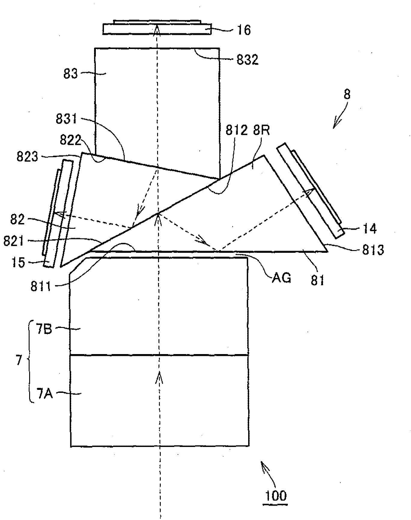
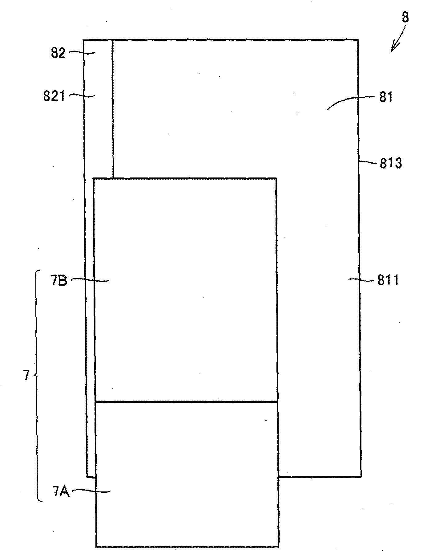
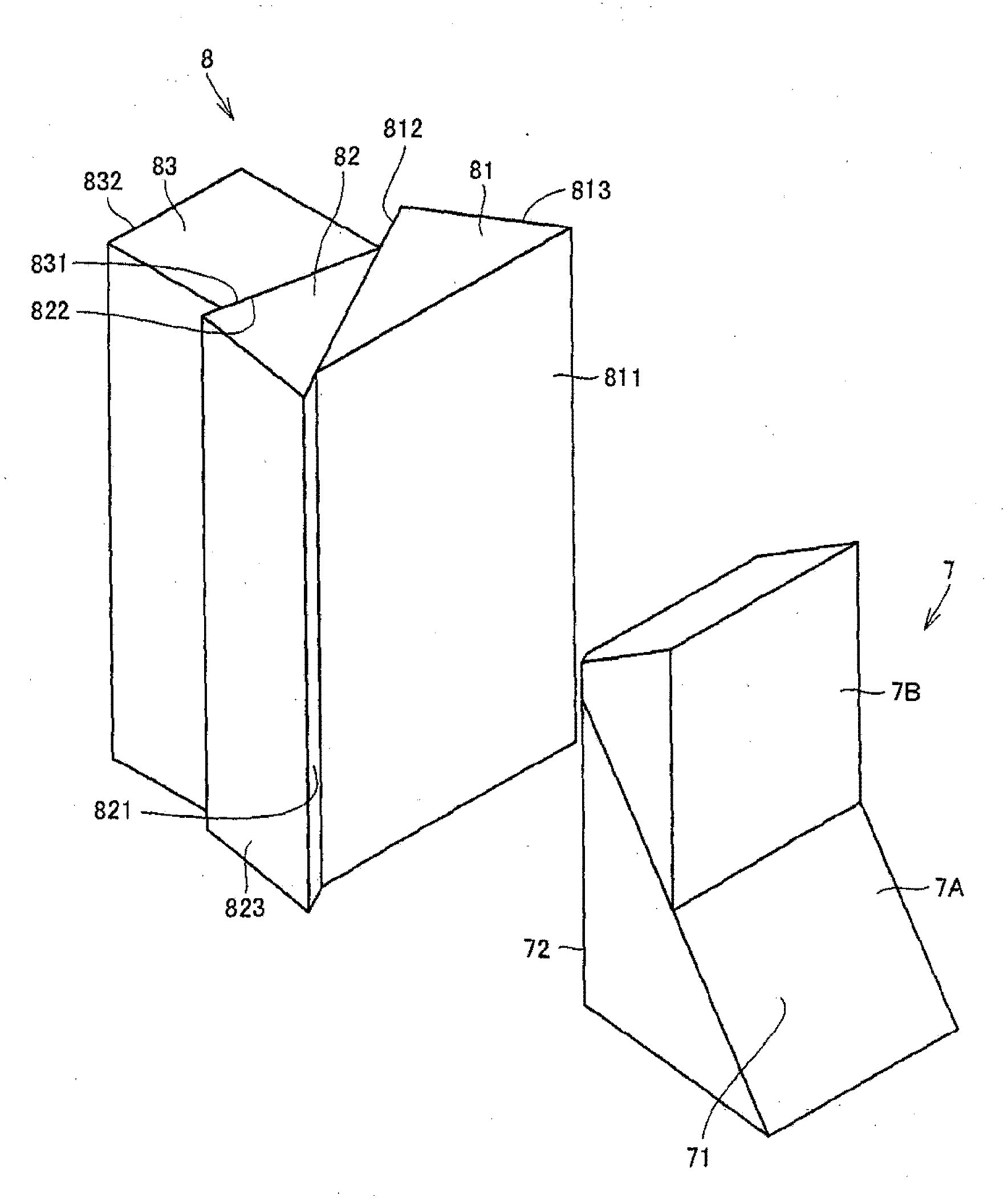
[0040] First, refer to Figure 1 to Figure 3 The basic configuration of the prism unit 100 used in the projection display device in this embodiment will be described. figure 1 is a top view of the prism unit 100, figure 2 is the front view of the prism unit, image 3 is a perspective view of the prism unit. Among them, in this specification, for the convenience of description, in Figure 1 to Figure 3 In the description, a plane parallel to the paper surface is defined as a horizontal direction, and a direction perpendicular to the paper surface is defined as a vertical direction.

[0041] (prism unit 100)

[0042]This prism unit 100 has an internal total reflection prism (TIR prism) 7 and a color separation and synthesis prism for guiding the illumination light IL to the first reflective display element 14, the second reflective display element 15, and the third reflective display element 16. 8. The prism unit 100 in this embodiment is a five prism unit.

[0043] The ...

Embodiment approach )

[0074] Next, refer to Figure 15 to Figure 19 The case where another antireflection film is used will be described. Figure 15 It is a figure showing another film structure of the antireflection film formed on each prism end face, Figure 16 It is a graph showing the refractive index of the film constituent material of the antireflection film with respect to each wavelength.

[0075] in addition, Figure 17 is used Figure 15 In the case of the anti-reflection coating for blue light whose peak wavelength of light is 465nm, the graph shows the results of measuring the reflectance in the range of angle of incidence (AOI) from 0° to 60°, Figure 18 is used Figure 15 In the case of the anti-reflection coating for green light with a peak wavelength of light of 532nm shown, the graph shows the results of measuring the reflectance in the range of angle of incidence (AOI) from 0° to 60°, Figure 19 is used Figure 15 In the case of the anti-reflection coating for red light whos...


PUM

PropertyMeasurementUnit
wavelengthaaaaaaaaaa

Abstract

The invention relates to a color decomposing compound prism whose reflective display element disposed opposite to a prism face having low reflectivity to not only lighting light and projection light and also to light having large incoming angles such as OFF. The color decomposing compound prism is provided with anti-reflection films (AR1, AR2, AR3) arranged on prism end faces (813, 823, 833) of the prism blocks (81, 82, 83) arranged opposite to the reflective display element (14, 15, 16). At least one of the anti-reflection films (AR1, AR2, AR3) is a low-reflection anti-reflection film whose maximum reflection rate of the reflection display element (14, 15, 16) is lower than 2% in an incoming angle range from 0 to 60 degrees.

Description

technical field [0001] The present invention relates to a color separation and synthesis prism used in a projection display device including a reflective display element such as a digital micromirror device (DMD). Background technique [0002] In a projection display device including a reflective display element such as a digital micromirror device (DMD), a prism unit that combines a color separation and synthesis prism and a total internal reflection prism (TIR prism) is used. [0003] The illumination light from the light irradiation mechanism enters the color separation and synthesis prism via the TIR prism. The color separation and synthesis prism decomposes the illumination light into blue light, red light, and green light and makes it incident on each reflective display element. In addition, the light reflected by the reflective display element is combined by the color separation and synthesis prism and exits as projection light to the projection optical system via th...

Claims


Application Information

Patent Timeline
Patent Type & Authority Applications(China)
IPC IPC(8): G02B27/10G02B5/04G02B1/11
Inventor 寺田昌弘高原浩滋
Owner KONICA MINOLTA INC
Learn More