Eureka AIR delivers breakthrough ideas for toughest innovation challenges, trusted by R&D personnel around the world.

A pipe holding device

A technology for clamping devices and pipes, applied in packaging, transportation and packaging, external frames, etc., can solve problems such as loss, oil elbow shaking, cable breakage, etc., to reduce wear, improve service life, and facilitate maintenance.

Active Publication Date: 2016-07-06
CHENGDU ZHIRONG ZHICHUANG INTPROP MANAGEMENT CO LTD
View PDF6 Cites 0 Cited by
  • Summary
  • Abstract
  • Description
  • Claims
  • Application Information

AI Technical Summary

Problems solved by technology

Medium and long-distance oil transportation requires larger diameter pipelines, and the sealing performance of the pipeline must be guaranteed; at present, the transportation of large-diameter oil pipelines, especially the transportation of oil elbows with curved parts, is relatively difficult, and most companies generally use The cables are bundled and fixed for transportation, but when driving in areas with poor road conditions, the oil elbow often shakes, causing certain damage to the pipeline itself, and in severe cases, the cables may break and cause huge losses

Method used


Image

  • A pipe holding device
  • A pipe holding device
  • A pipe holding device

Examples


Embodiment

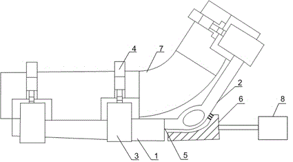
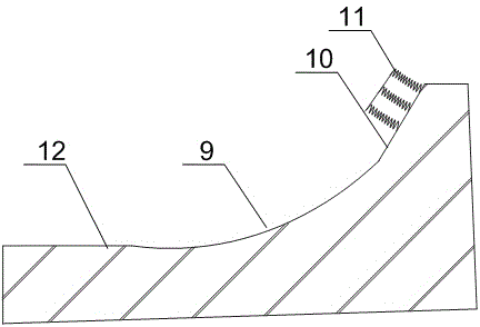
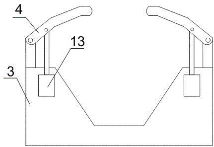
[0023] like Figure 1 to Figure 3 As shown, a pipe clamping device of the present invention includes a bottom plate 1 and an adjusting plate 2 arranged obliquely, a connecting plate 5 is arranged at the end of the bottom plate 1, and the bottom end of the connecting plate 5 and the adjusting plate 2 Hinged, fixed block 3 is installed on the bottom plate 1 and the adjustment plate 2, the fixed block 3 is U-shaped, the fixed block 3 is connected with the bottom plate 1 and the adjustment plate 2 by bolts, and also includes a pressure plate 4, the pressure plate 4 is hinged with the upper end of the fixed block 3, and a hydraulic cylinder 13 is also installed in the fixed block 3, and the telescopic end of the hydraulic cylinder 13 is connected with the middle part of the pressure plate 4. A limit mechanism is also provided; the limit mechanism includes a limit base 6 and a cylinder 8, and the limit base 6 is provided with an inclined surface 10 and a horizontal surface 12, and t...


PUM


Abstract

The invention discloses a pipe clamping device comprising a bottom plate and a slanting adjusting plate. A connecting plate is connected to the end of the bottom plate and hinged to the bottom end of the adjusting plate. Both the bottom plate and the adjusting plate are provided with fixing blocks which are U shaped. The fixing blocks are connected with the bottom plate and the adjusting plate through bolts. The pipe clamping device further comprises a pressure plate. The pressure plate is hinged to the upper ends of the fixing blocks. A hydraulic cylinder is disposed in each fixing block. The telescoping end of each hydraulic cylinder is connected to the middle of the pressure plate. The part of the connecting plate, hinged to the adjusting plate, is provided with a limit mechanism. The limit mechanism disposed at the part, hinged to the connecting plate, of the adjusting plate can stably support the adjusting plate which is under stress, and can also control the range of the included angle between the adjusting plate and the connecting plate; the adjusting plate is prevented from continuously moving down and failing to support, under extrusion of a bent part of an oil bend.

Description

technical field [0001] The invention relates to a clamping mechanism, in particular to a pipeline clamping device. Background technique [0002] Pipeline transportation is not only large in volume, continuous, rapid, economical, safe, reliable, stable, low in investment, small in land occupation, low in cost, and can be automatically controlled. In addition to being widely used in long-distance transportation of oil and natural gas, it can also For the transportation of ore, coal, building materials, chemicals and food, pipeline transportation can save the transfer of water or land transportation, shorten the transportation cycle, reduce transportation costs, and improve transportation efficiency. The current development trend of pipeline transportation is: the caliber of the pipeline is increasing continuously, and the transportation capacity is greatly improved; the transportation distance of the pipeline is increasing rapidly; the transportation materials are gradually ex...

Claims


Application Information

Patent Timeline
Patent Type & Authority Patents(China)
IPC IPC(8): B65D59/00B65D61/00B65D85/20
Inventor 贺昶明
Owner CHENGDU ZHIRONG ZHICHUANG INTPROP MANAGEMENT CO LTD
Why Eureka
Eureka Blog
Learn More