
A LED display module fixing device

A technology of LED display screen and fixing device, applied in the direction of fixing device, identification device, instrument, etc., can solve the problems of inconvenient maintenance, disassembly and installation, and achieve the effect of convenient operation and time saving.

Inactive Publication Date: 2016-08-17
FUJIAN HIGREEN CAILIANG OPTOELECTRONICS TECHCO LTD
View PDF7 Cites 0 Cited by
  • Summary
  • Abstract
  • Description
  • Claims
  • Application Information

AI Technical Summary

Problems solved by technology

[0004] The technical problem to be solved by the present invention is to provide a LED display module fixing device, which solves the problem of inconvenient maintenance, disassembly and installation caused by screw fixing in the prior art

Method used


Image

  • A LED display module fixing device
  • A LED display module fixing device

Examples


Embodiment Construction

[0018] The technical scheme of the present invention is described in detail below in conjunction with accompanying drawing and embodiment:

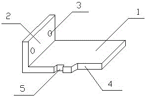
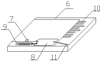
[0019] Such as figure 1 , figure 2 As shown, a LED display module fixing device includes a fixing plate 1 and a fixing slot 6, the fixing plate 1 includes a bending portion 2, and a first bayonet 4 is provided on one side of the fixing plate 1 , the second bayonet 5, the first bayonet 4 is arranged on the front end of the fixing plate 1, the second bayonet 5 is arranged between the first bayonet 4 and the bending part 2, and the bending part 2 is provided with a fixing hole 3 ; The inside of the fixed slot 6 is provided with a tenon 7, a slide block 8, a first spring 9, a second spring 10, and a lever 11. First spring 9, slide block 8, lever 11 are arranged in sequence, and described first spring 9 is connected with slide block 8; One end of described lever 11 is connected with second spring 10, and the other end is movably connected w...


PUM


Abstract

The invention discloses a LED display module fixing device, comprising a fixing plate and a fixing slot, the fixing plate includes a bending portion, and a first bayonet and a second bayonet are arranged on one side of the fixing plate , the first bayonet is arranged on the front end of the fixing plate, the second bayonet is arranged between the first bayonet and the bending part, and the bending part is provided with a fixing hole; the inside of the fixing groove is provided with a chute and a tenon , a slider, a first spring, a second spring, and a lever; when the fixed plate is located in the fixed slot, the first bayonet fits the slider, and the tenon is located in the second bayonet. By installing the fixing device on the module, you only need to install the fixing plate of the device on the module, and install the fixing card slot on the box body. There is no need for a lot of screwing process, which saves time and is convenient. operate.

Description

technical field [0001] The invention discloses a LED display screen module fixing device, which belongs to the field of LED display screen application accessories. Background technique [0002] As a fast-growing industry, the LED display industry, while its application brings convenience to people, there must be great room for improvement. For example, there are still many unreasonable or inconvenient aspects in the manufacturing process. [0003] At present, the fixing method of the LED display module is mainly to set multiple screw holes on the box body or on the aluminum profile. When assembling, it takes a lot of screwing time to fix the module to the box body or the aluminum profile. The display module installed by this method is relatively firm, but there are also some problems. For example, when the display module has a problem or fails, it needs to be removed for maintenance again. This is only before the product leaves the factory. The work that can be done, once t...

Claims


Application Information

Patent Timeline
Patent Type & Authority Patents(China)
IPC IPC(8): G09F9/33F16B1/04
Inventor 林建忠
Owner FUJIAN HIGREEN CAILIANG OPTOELECTRONICS TECHCO LTD
Learn More