
Film magazine monitoring system

A monitoring system and cassette technology, applied in electrical components, semiconductor/solid-state device manufacturing, circuits, etc., can solve problems such as failure to detect abnormal mechanical stepping motors in time, large-area wafer damage, and wafer damage.

Active Publication Date: 2014-03-12
SHANGHAI HUAHONG GRACE SEMICON MFG CORP
View PDF8 Cites 13 Cited by
  • Summary
  • Abstract
  • Description
  • Claims
  • Application Information

AI Technical Summary

Problems solved by technology

During this process, if the cassette on the loading platform is tilted, when the manipulator takes the wafer from the cassette or places the wafer into the cassette, it will collide with the adjacent wafer and the wafer will be damaged.
[0004] The conventional monitoring system of the film cassette is realized by physical contact with the film cassette. It is impossible to monitor the tilt of the cassette caused by the deformation of the cassette and the incomplete physical contact caused by the deformation.
In addition, there is also a lack of monitoring during the movement of the manipulator to the cassette to pick and place wafers, resulting in occasional mechanical stepping motor abnormalities that cannot be detected in time, easily causing large-area wafer damage

Method used


Image

  • Film magazine monitoring system
  • Film magazine monitoring system
  • Film magazine monitoring system

Examples


Embodiment 1

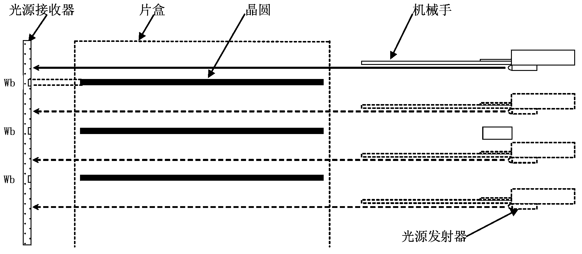
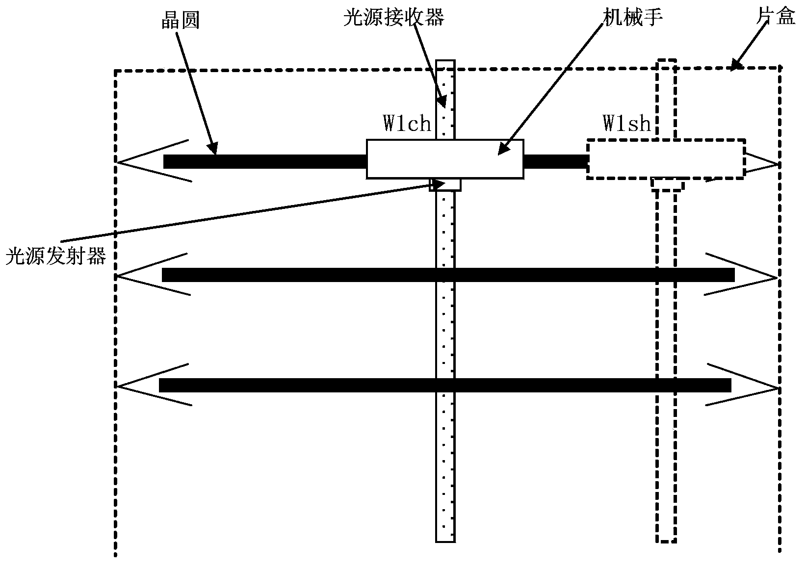
[0028] Cassette monitoring systems such as figure 2 , image 3 As shown, including loading platform, manipulator, light source transmitter, light source receiver, processor;

[0029] The loading platform is used to place the cassette;

[0030] The manipulator is located on one side of the loading platform, and is used to pick and place wafers in the cassettes placed on the loading platform;

[0031] The light source emitter is fixed on the manipulator and is used to emit light parallel to the plane of the manipulator to the other side of the loading platform;

[0032] The light source receiver is arranged on the other side of the loading platform, and is used to receive the light emitted by the light source emitter, and output the light emitted by the light source emitter. The height Wch of the central point of the wafer blocking area, and the height Wsh of the side points of the wafer blocking area;

[0033] The processor is configured to output the thickness Wt of the b...

Embodiment 2

[0040] The light source emitter emits light parallel to the plane of the manipulator when the manipulator moves between the wafers in the cassette;

[0041] The light source receiver, when receiving light, also outputs a light arrival signal to the processor;

[0042] The processor, if the light arrival signal is not received within a set time after the movement of the manipulator to the wafers in the cassette, the processor outputs a manipulator failure alarm signal;

[0043] Such as Figure 6 As shown, when the manipulator moves between the wafers in the cassette, the light source emitter emits light parallel to the plane of the manipulator. If the manipulator is normal, the light parallel to the plane of the manipulator is also parallel to the wafers in the cassette On the upper and lower surfaces, the light emitted by the light source transmitter will pass through the gap between the manipulator and the wafer surface, and be received by the light source receiver on the op...


PUM


Abstract

The invention discloses a film magazine monitoring system comprising a light source emitter, a light source receiver and a processor. The light source emitter is fixed on a mechanical hand and used for emitting light rays, which are parallel to the surface of the mechanical hand, to the other side of a loading platform. The light source receiver is arranged on the other side of the loading platform and used for receiving the light rays emitted by the light source emitter and outputting thickness of an area, which is blocked by a wafer, of the light rays emitted by the light source emitter, central point height of the area, which is blocked by the wafer, of the light rays emitted by the light source emitter, and height of one side point of the area, which is blocked by the wafer, of the light rays emitted by the light source emitter. The processor is used for outputting an alarm signal indicating forward and backward inclination or leftward and rightward inclination according to the thickness of the area blocked by the wafer, the central point height of the area blocked by the wafer, and the height of one side point of the area blocked by the wafer. The film magazine inclination state can be accurately monitored by the film magazine monitoring system.

Description

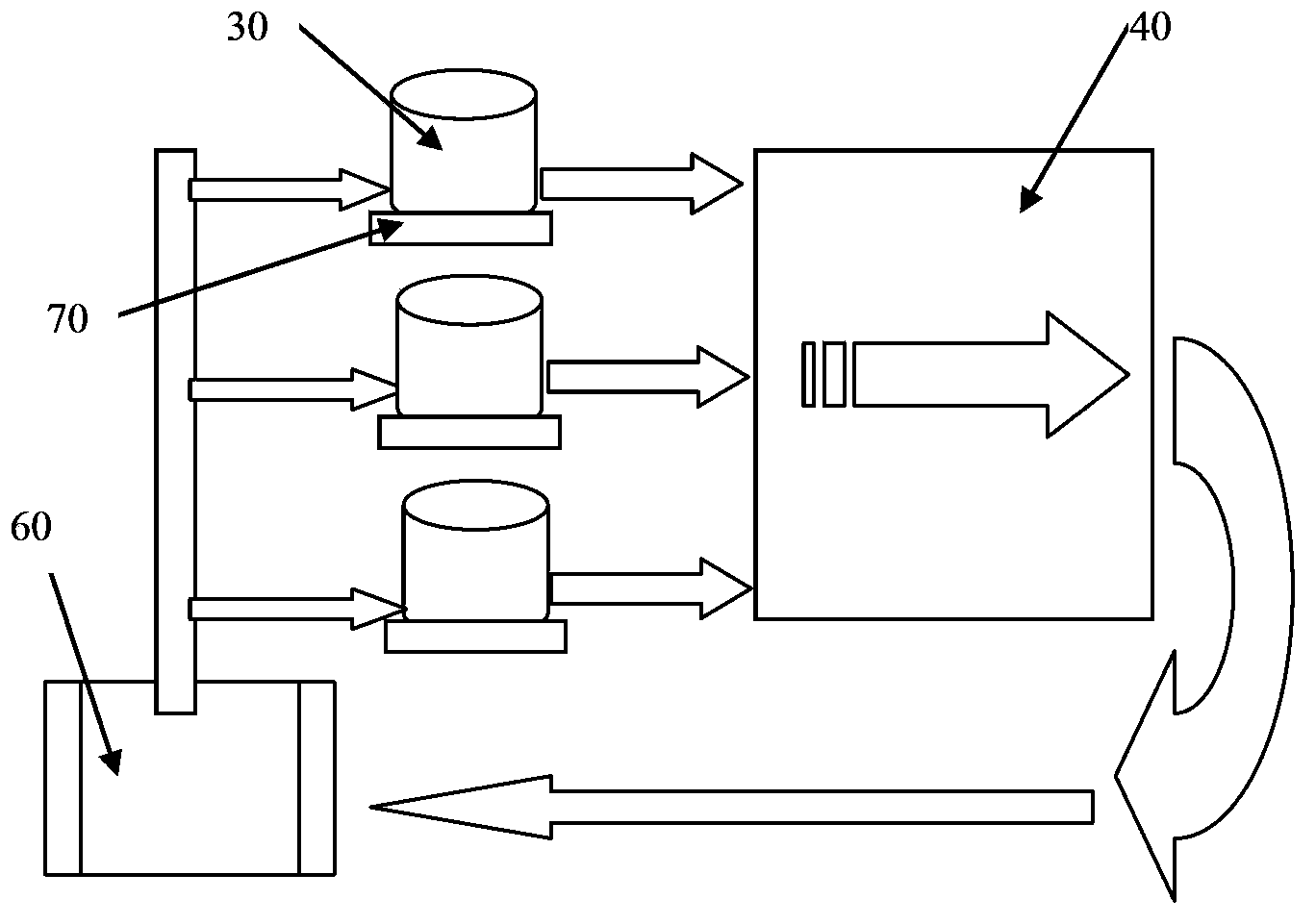
technical field [0001] The invention relates to wafer processing equipment, in particular to a cassette monitoring system. Background technique [0002] Common wafer processing equipment, such as WJ 1000H (a wafer processing equipment product name of Watkins Johnson), such as figure 1 As shown, it includes a loading platform 70 , a control system, a manipulator, a wafer conveyor belt, a process chamber 40 , and a return platform 60 . The arrows in the figure indicate the transmission line of the wafer. The wafer is placed in the cassette 30 and loaded onto the loading platform 70. Then the manipulator picks up the wafer, and sends the taken wafer into the wafer in the process chamber 40 inside the equipment. Processed on the circular conveyor belt, the processed wafers are sequentially delivered to the return platform 60 at the end of the equipment by the conveyor belt, taken out by the manipulator, and put back into the cassette 30 on the loading platform 70 . [0003] Th...

Claims


Application Information

Patent Timeline
Patent Type & Authority Applications(China)
IPC IPC(8): H01L21/67
CPCH01L21/67259
Inventor 沈坚
Owner SHANGHAI HUAHONG GRACE SEMICON MFG CORP
Learn More