Self-Calibrating Harmonic Current Transformer Based on Gap Core Coil
What is Al technical title?
Al technical title is built by PatSnap Al team. It summarizes the technical point description of the patent document.
An iron core coil and harmonic current technology, applied in voltage/current isolation, instrumentation, measurement of electrical variables, etc., can solve problems such as inability to overcome the measurement frequency band and affect the accuracy of current detection
Active Publication Date: 2015-10-21
ZHEJIANG HORIZON INSTR TRANSFORMERS
View PDF11 Cites 4 Cited by
Summary
Abstract
Description
Claims
Application Information
AI Technical Summary
This helps you quickly interpret patents by identifying the three key elements:
Problems solved by technology
Method used
Benefits of technology
Problems solved by technology
The disadvantage of this technical solution is that the use of air gap and shielding coil can only reduce the influence of leakage magnetic field so that the iron core is not suitable for saturation, but it cannot overcome the problem of narrow measurement frequency band and can only be used under power frequency
The disadvantage of this technical solution is that although the air-core coil is wound on the skeleton, there will still be changes in its geometric dimensions due to factors such as ambient temperature during long-term operation, which will seriously affect the accuracy of current detection.
Method used
Image
Click on the blue label to locate the original text in one second.
Reading with bidirectional positioning of images and text.
Examples
Embodiment
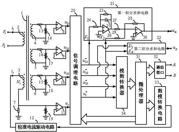
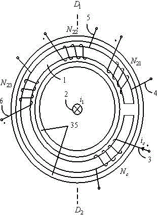
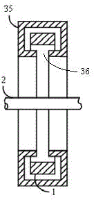
[0050] Example: as figure 1 , figure 2 , image 3 As shown, the present invention is a self-calibrating harmonic current transformer based on a gapped iron core coil.
[0051] Iron core with gap (ring) 1, primary coil 2, secondary coil 4 for measurement, secondary coil 5 for protection, secondary coil 6 for monitoring, calibration coil 3 and annular shielding box 35 with slotted inner ring constitute the primary current Sensor; the secondary coil 4 for measurement, the secondary coil 5 for protection, the secondary coil 6 for monitoring and the calibration coil 3 are uniformly wound on the annular iron core 1 with a gap to form an annular core coil; the sampling resistor 7 is used A purely resistive precision resistor with a resistance value of 1KΩ and a temperature drift rate lower than 5ppm / °C; the digital-analog signal amplifier circuit 12 adopts a single-tube common-emitter amplifier circuit; Groove 36; communication interface 32 is RS485 communication interface.
[0...
PUM
Abstract
The invention discloses a self-calibration harmonic current transformer based on a gapped iron core coil. The transformer can output digital quantity and voltage simulation quantity which are linearly proportional to primary current containing harmonics, and can achieve the purposes of measurement and protection. The self-calibration harmonic current transformer comprises a gapped iron core, a primary coil, a measurement secondary coil, a protection secondary coil, a calibration coil, a monitoring secondary coil, an annular shielding box with a slotted inner ring, a first resistor, a second resistor, a third resistor, a sampling resistor, a first operational amplifier, a second operational amplifier, a third operational amplifier, a fourth operational amplifier, a first bidirectional voltage regulator tube, a second bidirectional voltage regulator tube, a third bidirectional voltage regulator tube, a fourth bidirectional voltage regulator tube, a signal conditioning circuit, an analog-to-digital converter, a microprocessor, a digital-to-analog conversion circuit, a calibration current drive circuit, a communication interface, and a first integral summation circuit and a second integral summation circuit which use a lossy integrator.
Description
technical field [0001] The invention relates to an electromagnetic measuring device, in particular to a self-calibrating harmonic current transformer based on an iron core coil with a gap for dual purposes of measurement and protection. Background technique [0002] Current transformer is a kind of current sensor, which is mainly used for grid electric energy measurement, electric energy quality analysis and safety protection. The national standard GB 1208-2006 "Current Transformer" and GB / T20840.8-2007 "Transformer Part 8 Electronic Current Transformer" stipulate the technical specifications of electromagnetic current transformer and electronic current transformer respectively. The national standard GB / T14549-1993 "Power Quality Harmonics of Public Grid" and the national standard GB / T19862-2005 "General Requirements for Power Quality Monitoring Equipment" respectively stipulate the allowable value, detection method and current harmonic monitoring equipment of public grid ha...
Claims
Application Information
Patent Timeline
Application Date:The date an application was filed.
Publication Date:The date a patent or application was officially published.
First Publication Date:The earliest publication date of a patent with the same application number.
Issue Date:Publication date of the patent grant document.
PCT Entry Date:The Entry date of PCT National Phase.
Estimated Expiry Date:The statutory expiry date of a patent right according to the Patent Law, and it is the longest term of protection that the patent right can achieve without the termination of the patent right due to other reasons(Term extension factor has been taken into account ).
Invalid Date:Actual expiry date is based on effective date or publication date of legal transaction data of invalid patent.