
Vertical type flying probe tester clamp and design method thereof

A technology of flying probe testing machine and fixture, which is applied in the direction of the casing of the measuring device, can solve the problems of high production cost, uneven clamping force, and inconvenient operation, and achieve the effects of convenient operation, prevention of random rotation, and reduction of manufacturing cost

Active Publication Date: 2014-03-05
HANS CNC SCI & TECH
View PDF6 Cites 12 Cited by
  • Summary
  • Abstract
  • Description
  • Claims
  • Application Information

AI Technical Summary

Problems solved by technology

[0005] Based on this, it is necessary to solve the problems of uneven clamping force, inconvenient operation and high production cost of traditional clamps, and provide a vertical flying probe testing machine fixture with uniform clamping force, convenient operation and low cost and its design method

Method used

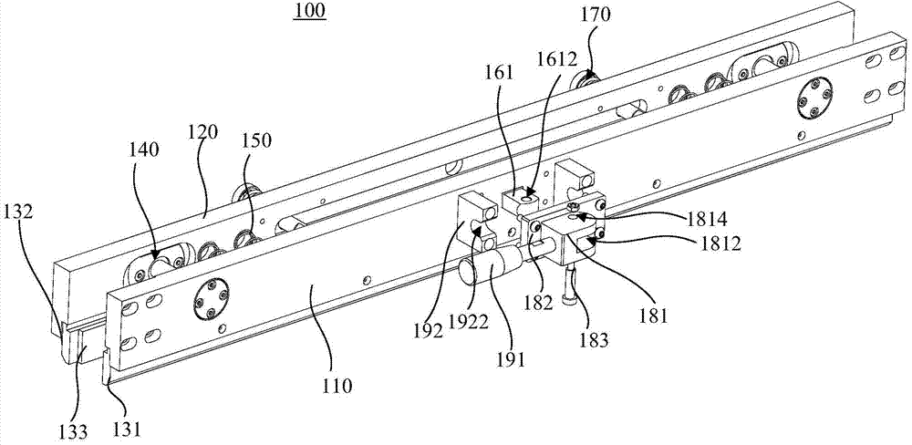

Image

  • Vertical type flying probe tester clamp and design method thereof
  • Vertical type flying probe tester clamp and design method thereof
  • Vertical type flying probe tester clamp and design method thereof

Examples


Embodiment Construction

[0044] In order to make the above objects, features and advantages of the present invention more comprehensible, specific implementations of the present invention will be described in detail below in conjunction with the accompanying drawings. In the following description, numerous specific details are set forth in order to provide a thorough understanding of the present invention. However, the present invention can be implemented in many other ways different from those described here, and those skilled in the art can make similar improvements without departing from the connotation of the present invention, so the present invention is not limited by the specific implementations disclosed below.

[0045] It should be noted that when an element is referred to as being “fixed” to another element, it can be directly on the other element or there can also be an intervening element. When an element is referred to as being "connected to" another element, it can be directly connected ...


PUM


Abstract

A vertical type flying probe tester clamp is used for clamping a PCB, and comprises a fixed board, a movable board, a first clamp bar, a second clamp bar, a guide component, an auxiliary spring, a connecting rod component, a limiting component and a drive component. When the clamp is in an open state, the auxiliary spring and a limiting spring are both in a compression state, the drive component drives the connecting rod component to move in the direction close to the fixed board, the connecting rod component drives the limiting component to move in the direction close the fixed board, the limiting spring applies pressure to the movable board to enable the movable board to move in the direction close the fixed board, the distance between the fixed board and the movable board is gradually reduced until the PCB is clamped, the pressure applied by the limiting spring is evenly dispersed to the movable board in a fixed mode, and even clamping force is applied to the PCB. When an object does not need to be clamped, the drive component only needs to move in the opposite direction, the object can be unloaded, and the operation is convenient. Meanwhile, a design method of the vertical type flying probe tester clamp is provided.

Description

technical field [0001] The present invention relates to the technical field of printed circuit board (Printed circuit board, PCB) fixing devices, in particular to a fixture for a vertical flying probe testing machine and a design method thereof. Background technique [0002] The flying probe testing machine is installed on the X-Y axis with an independent and fast-moving probe driven by a motor, and uses the controllable movement of the probe in the Z direction to make contact with the solder joints of the printed circuit board (PCB) fixed on the machine. , and equipment for making electrical measurements. [0003] When the PCB board of the vertical flying probe tester is fixed, the upper end of the PCB board is generally fixed by the upper clamp, and the lower end of the PCB board is fixed by the lower clamp. The main structure of the upper and lower fixtures is generally the same, and the lower fixture is usually equivalent to placing the upper fixture upside down. [00...

Claims


Application Information

Patent Timeline
IPC IPC(8): G01R1/04
Inventor 谭艳萍王星宋福民翟学涛杨朝辉高云峰
Owner HANS CNC SCI & TECH
Learn More