Floating connector

A technology of floating connectors and connectors, which is applied in the direction of connection, parts of connection devices, electrical components, etc., to achieve the effect of novel structure and convenient mating

Active Publication Date: 2014-02-26
CHINA ELECTRONICS TECH GRP NO 23 RES INST
View PDF4 Cites 6 Cited by
  • Summary
  • Abstract
  • Description
  • Claims
  • Application Information

AI Technical Summary

Problems solved by technology

For floating connectors to be installed on panels that require two angles to rotate butt joints, conventional floating connectors cannot meet such installation requirements

Method used


Image

  • Floating connector
  • Floating connector
  • Floating connector

Examples


Embodiment Construction

[0023] In order to further explain the technical means and effects of the present invention to achieve the intended purpose of the invention, the specific implementation, structure, features and effects of the floating connector proposed according to the present invention will be described in detail below in conjunction with the accompanying drawings and preferred embodiments. The description is as follows.

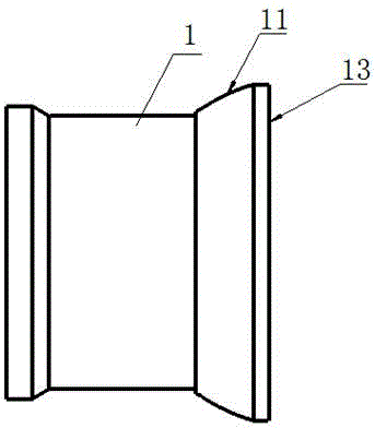
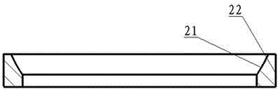
[0024] Such as Figure 5 As shown, a floating connector of the present invention includes a floating inner casing 1 , an arc sleeve 2 , a connector casing 3 , a wave spring 4 , a pin 5 and a tree spring group 6 .

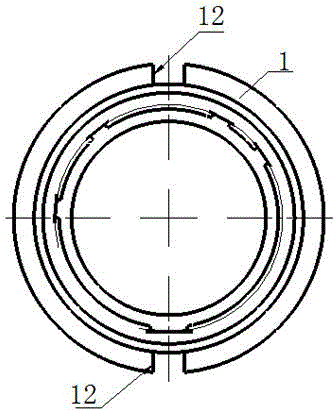
[0025] Such as figure 1 with figure 2 As shown, the floating inner shell 1 is a cylindrical structure, and the outer side of the cylindrical tail is a spherical structure 11 protruding outward. As the rotating structure of the floating inner shell 1, two The straight groove 12 is used to fix the rotation direction of the floating inner shell 1 .

[0026] S...


PUM


Abstract

The invention relates to a floating connector. A structure of the floating connector comprises an outer connector casing, an inner floating casing, an arc sleeve and a connection member, wherein an outer side of a tail portion of the inner floating casing is a spherical structure, an end face of the tail portion of the inner floating casing is provided with symmetrical straight slots in a radial direction, an inner side of the arc sleeve is a spherical inner wall which is in matching with an outer spherical structure of the tail portion of the inner floating casing, mutual rotation can be realized, the connection member penetrates through the outer connector casing and is plugged in the straight slots of the inner floating casing, elastic members with different heights at two ends are arranged between the outer connector casing and the inner floating casing, and an axial line of the inner floating casing and an axial line of the outer connector casing have a deflection angle and are superposed when rotation to a certain angle is realized. According to the floating connector, a spherical angle rotation structure is utilized, blind plugging requirements for two angle-rotation abut panels are effectively satisfied, when the panels are mounted and dimension deviation occurs in a product, position correction of one floating end can be carried out automatically, and thereby smooth plugging of a fixedly-mounted plug or socket can be realized.

Description

technical field [0001] The invention relates to a connector, in particular to a floating connector. technical background [0002] The connector is composed of two connectors that can be plugged and connected. The most commonly used connector is composed of two connectors, a plug and a socket. The plug is generally not fixed at the free end, while the socket is fixed. However, in some special occasions, the plug and socket must be fixedly installed on the panel, and the connector needs to be driven by the installation panel to insert the plug or socket with the other end when mating. Due to the size deviation of the installation panel and the product, it is difficult for the plug and socket fixedly installed on the panel to be mated smoothly. Therefore, there must be a certain amount of floating at one end of the plug or socket of the connector. When the plug and socket are docked, the floating end It can automatically perform position correction, so that it can be mated sm...

Claims


Application Information

Patent Timeline
Patent Type & Authority Applications(China)
IPC IPC(8): H01R13/631
Inventor 葛雄浩苏建
Owner CHINA ELECTRONICS TECH GRP NO 23 RES INST
Why Eureka
Try Eureka