High-resolution dbs imaging method based on joint multi-wavelength

An imaging method and high-resolution technology, which is applied in the field of radar, can solve the problems that cannot meet the high-resolution observation requirements of the carrier aircraft and low azimuth resolution, and achieve the effect of increasing the number of coherent accumulation pulses and improving the resolution

Active Publication Date: 2015-09-30
XIDIAN UNIV
View PDF5 Cites 0 Cited by
  • Summary
  • Abstract
  • Description
  • Claims
  • Application Information

AI Technical Summary

Problems solved by technology

In essence, DBS imaging in scanning mode is non-focused imaging, so its azimuth resolution is relatively low compared with strip mode and spotlight mode, and it cannot meet the high-resolution observation requirements of carrier aircraft to the ground

Method used


Image

  • High-resolution dbs imaging method based on joint multi-wavelength
  • High-resolution dbs imaging method based on joint multi-wavelength
  • High-resolution dbs imaging method based on joint multi-wavelength

Examples


Embodiment Construction

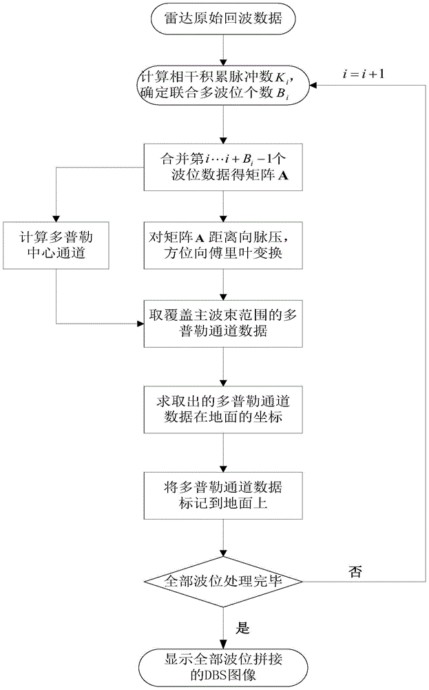
[0032] refer to figure 1 , the specific implementation steps of the present invention are as follows:

[0033] Step 1. Install the radar on the aircraft. The normal direction of the radar plane is perpendicular to the direction of the aircraft fuselage. The radar performs mechanical scanning during the flight of the aircraft, and the scanning wave position changes with time. The radar scans a total of N Wave position, N≥2; the initial wave position of the radar start-up scan is taken as the first wave position, and the radar records the ground echo data once for each wave position scanned.

[0034] Step 2, take the projected position of the aircraft on the ground when the radar is at the first wave position as the origin O 1 , the flight direction of the aircraft is the X axis, and the Y axis is perpendicular to the flight direction of the aircraft, and the ground coordinate system X corresponding to the first wave position is established 1 o 1 Y 1 , in the ground coordina...


PUM


Abstract

The invention discloses a high-resolution DBS imaging method based on multiple united wave positions. The high-resolution DBS imaging method mainly solves the problem that an existing DBS is low in imaging resolution. The implementation process of the high-resolution DBS imaging method comprises the following steps: (1) the number of radar coherent integration pulses and the number of the wave positions which need to be united are calculated according to time for a radar to irradiate a ground point target; (2) data of the multiple wave positions of the radar are merged according to the number of the wave positions which need to be united; (3) the merged data are subjected to pulse compression in distance and Fourier transformation in azimuth to obtain Doppler channel data; (4) the part, corresponding to a main beam range of the radar, in the Doppler channel data is extracted, and ground coordinates of the data in the corresponding part are calculated; (5) the data of the main beam range of the radar are marked on the ground to obtain an image according to the obtained ground coordinates. By means of the high-resolution DBS imaging method based on the multiple united wave positions, mechanical scanning can be conducted through the radar in the flying process of a plane so as to image the ground, the resolution of the image is greatly increased, and the high-resolution DBS imaging method can be applied to detection and positioning of a ground moving target.

Description

technical field [0001] The invention belongs to the field of radar technology, in particular to a high-resolution Doppler beam sharpening DBS imaging method, which can be used for target detection and tracking. Background technique [0002] Radar was developed by military needs in World War II. It was originally used to track aircraft and ships in bad weather and in the dark. Early radar systems used time delays to measure the distance between the radar and the target, thereby tracking and monitoring the target. . With the development of related technologies, radar applications are no longer limited to simple tracking of targets. At present, classifying and identifying target types and obtaining high-resolution image information within the surveillance range have become new hotspots in radar research. [0003] In June 1951, Carl Wiley of the American Goodyear Company proposed for the first time the method of improving the azimuth resolution of the moving platform radar by p...

Claims


Application Information

Patent Timeline
Patent Type & Authority Patents(China)
IPC IPC(8): G01S13/89
CPCG01S7/415G01S13/522G01S13/9029
Inventor 王彤吴晓明吴建新吴亿锋
Owner XIDIAN UNIV
Why Eureka
Try Eureka