Eureka AIR delivers breakthrough ideas for toughest innovation challenges, trusted by R&D personnel around the world.

Anti-winding flap type rudder guide rod transmission device

A technology of guide rod transmission and transmission device, which is applied in rudder steering and other directions, can solve the problems of reducing the service life of the transmission device, consuming the energy of the steering gear, increasing the friction force of the guide rod device, etc., and achieves prolonging the service life, simple structure, The effect of easy installation and removal

Inactive Publication Date: 2014-02-26
江苏华帝海洋工程设备制造有限公司
View PDF6 Cites 0 Cited by
  • Summary
  • Abstract
  • Description
  • Claims
  • Application Information

AI Technical Summary

Problems solved by technology

[0002] When the ship is sailing, due to the poor environment of the route, there are many sundries in the waters, such as fishing nets, ropes, etc. Once they are entangled by aquatic plants with deep roots, long grass, leafy leaves or abandoned fishing nets, they will become more and more entangled , getting tighter and tighter, so that the main engine cannot operate and is forced to stop
The structure design of the traditional transmission device is to fix the guide rod near the "bow" and keep sliding near the "stern". The wear of the guide rod not only affects the sensitivity of the transmission device, but also greatly increases the friction of the guide rod device, consumes the energy of the steering gear, increases the maintenance cost of the transmission device, and reduces the service life of the transmission device and even the rudder

Method used


Image

  • Anti-winding flap type rudder guide rod transmission device
  • Anti-winding flap type rudder guide rod transmission device
  • Anti-winding flap type rudder guide rod transmission device

Examples


Embodiment Construction

[0011] Below in conjunction with accompanying drawing, the present invention will be further described;

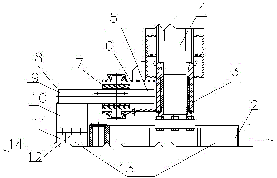
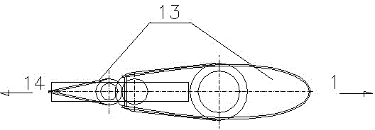
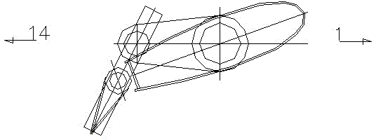
[0012] Anti-tangle flap rudder guide rod drive, incl. Guide rod 9, guide sleeve 7, fixing device 6, main rudder 2, It is characterized by: The fixed end 8 of the guide rod on the transmission device is designed in the direction of the stern 14 of the rudder blade 13, and the sliding end of the guide rod is arranged in the direction of the bow 1 of the rudder blade 13.

[0013] The transmission device is that the rudder stock protection cover 3 is arranged on the rudder stock 4, and the rudder stock protection cover 3 is provided with a fixing device 6 on one side of the stern 14 direction; between the fixing device 6 and the guide rod 9 A guide sleeve 7 with a pin positioned on the fixing device 6 is provided; the guide rod 9 is welded on the bracket 10; the bracket is fixed on the auxiliary rudder 11 by bolts 12

[0014] During specific implementation, as shown in the...


PUM


Abstract

An anti-winding flap type rudder guide rod transmission device comprises a guide rod, a guide sleeve, a fixing device and a main rudder. A guide rod fixing end on the transmission device is designed on a stern of a rudder blade, and a guide rod sliding end is designed in the ship bow direction of the rudder blade. According to the transmission device, a rudder stock protective sleeve is arranged on a rudder stock, and the fixing device is arranged on the side, in the stern direction, of the rudder stock protective sleeve. The guide sleeve located on the fixing device through a pin shaft is arranged between the fixing device and the guide rod. The guide rod is welded to a support. The support is fixed to an auxiliary rudder through bolts. The anti-winding flap type rudder guide rod transmission device is simple in structure, safe, reliable and easy and convenient to mount and dismount, the transmission guide rod fixing end is designed on the stern of the rudder blade, the sliding end is designed on a ship bow of the rubber blade, a fishing net behind a ship body or other sundries cannot be wound on the stern portion of the guide rod when the rudder blade rotates, the service life of the rudder is prolonged, and the anti-winding flap type rudder guide rod transmission device is widely suitable for ship rudder blades of all types.

Description

technical field [0001] The present invention relates to a Anti-tangle flap rudder guide rod drive, it is suitable for How to prevent the ship from being entangled by sundries when sailing belongs to the field of ship rudder system design. Background technique [0002] When the ship is sailing, due to the poor environment of the route, there are many sundries in the waters, such as fishing nets, ropes, etc. Once they are entangled by aquatic plants with deep roots, long grass, leafy leaves or abandoned fishing nets, they will become more and more entangled , the tighter and tighter the winding, so that the main engine cannot operate and is forced to stop. The structure design of the traditional transmission device is to fix the guide rod near the "bow" and keep sliding near the "stern". The wear of the guide rod not only affects the sensitivity of the transmission device, but also greatly increases the friction of the guide rod device, consumes the energy of the steering ge...

Claims


Application Information

Patent Timeline
Patent Type & Authority Applications(China)
IPC IPC(8): B63H25/10
Inventor 陈波戴建武
Owner 江苏华帝海洋工程设备制造有限公司
Why Eureka
Eureka Blog
Learn More