
Outfield testing device of airplane tail jet flow field

A field test, tail jet technology, applied in the testing of machine/structural components, measuring devices, aerodynamic tests, etc., can solve problems such as no engine jet test

Active Publication Date: 2014-02-12
XIAN AIRCRAFT DESIGN INST OF AVIATION IND OF CHINA
View PDF5 Cites 11 Cited by
  • Summary
  • Abstract
  • Description
  • Claims
  • Application Information

AI Technical Summary

Problems solved by technology

However, there is currently no device suitable for jet flow testing of aircraft engines in the field

Method used


Image

  • Outfield testing device of airplane tail jet flow field

Examples


Embodiment Construction

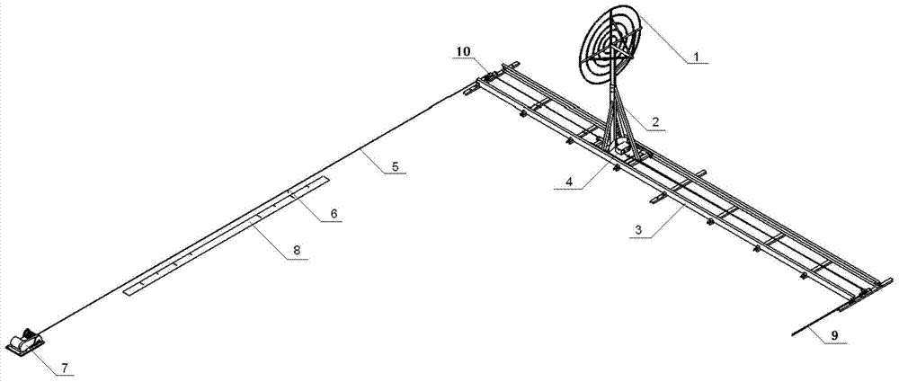
[0007] The present invention will be described in further detail below. see figure 1 , an outfield testing device for jet flow field of aircraft tail, comprising measuring rake 1, measuring rake support 2 and measuring signal collector, on which measuring rake 1 is installed a test sensor, the output end of the test sensor is connected to the measuring signal collector through wires The corresponding input terminal is connected; it is characterized in that: there is an outfield measurement rake installation mechanism composed of track 3, rail car 4, steel cable 5, pointer 6, hoist 7, ground scale 8, fixed pulley 10 and test device controller; Track 3 is composed of two steel rails and sleepers connected with the rails. Rail car 4 is located on track 3. Rail car 4 has a locking device that can be locked on track 3. The measuring signal collector is installed on rail car 4. Fixed pulley 10 is fixed at one end of track 3, winch 7 is positioned at the side of track 3, and the dis...


PUM


Abstract

The invention belongs to the testing technology of airplanes, and relates to an outfield testing device of an airplane tail jet flow field. The outfield testing device of the airplane tail jet flow field is characterized by comprising an outfield measurement rake installation mechanism, and the outfield measurement rake installation mechanism is composed of a track (3), a track car (4), a wirerope (5), a pointer (6), a winch (7), a ground scale (8), a fixed pulley (10) and a testing device controller. The outfield testing device of the airplane tail jet flow field meets the requirement for outfield airplane engine jet flow tests.

Description

technical field [0001] The invention belongs to the aircraft testing technology, and relates to an outfield testing device for an aircraft tail jet flow field. Background technique [0002] The test of jet flow field of aircraft engine tail is an important test of aircraft intake and exhaust design. In order to obtain the temperature field and velocity field of the exhaust jet, it can provide reliable parameter input for aircraft aerodynamic and structural design. At present, the engine jet flow test before installation is completed on the engine test bench. The measuring rake is installed on the measuring rake bracket, and the sensors required for the test, such as temperature sensors and pressure sensors, are installed on the measuring rake bracket. The signal output end of the sensor is connected with the signal input end of the measurement signal collector through wires. During the test, the measuring rake bracket is fixed at a certain distance behind the engine tail n...

Claims


Application Information

Patent Timeline
IPC IPC(8): G01M9/06
Inventor 吴宇钟剑龙刘苏彦练秋明
Owner XIAN AIRCRAFT DESIGN INST OF AVIATION IND OF CHINA
Learn More