
A thermostat for a heat exchange circuit

A thermostat and thermal circuit technology, applied in the direction of valve operation/release device, gear lubrication/cooling, valve details, etc., can solve the problems of low thermostat spring life, fluid leakage, high structural design requirements of thermostat, etc. , to achieve the effect of reducing fluid leakage points

Active Publication Date: 2016-05-25
ZHEJIANG SANHUA AUTOMOTIVE COMPONENTS CO LTD
View PDF9 Cites 0 Cited by
  • Summary
  • Abstract
  • Description
  • Claims
  • Application Information

AI Technical Summary

Problems solved by technology

[0005] The purpose of the present invention is to solve the problem that the spring of the thermostat in the prior art has a relatively low service life, the structural design requirements of the thermostat are relatively high, and the gap between the retaining ring and the thermal element causes a relatively large leakage of the actual fluid. Defects Provide a thermostat for a heat exchange circuit

Method used


Image

  • A thermostat for a heat exchange circuit
  • A thermostat for a heat exchange circuit
  • A thermostat for a heat exchange circuit

Examples


specific Embodiment approach

[0036] The orientation nouns such as top, bottom, left, and right described in the present invention are all described according to the relationship between up, down, left, and right in the accompanying drawings;

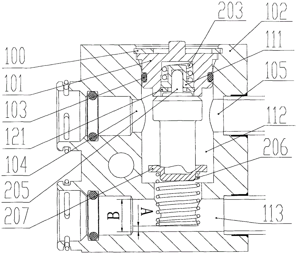
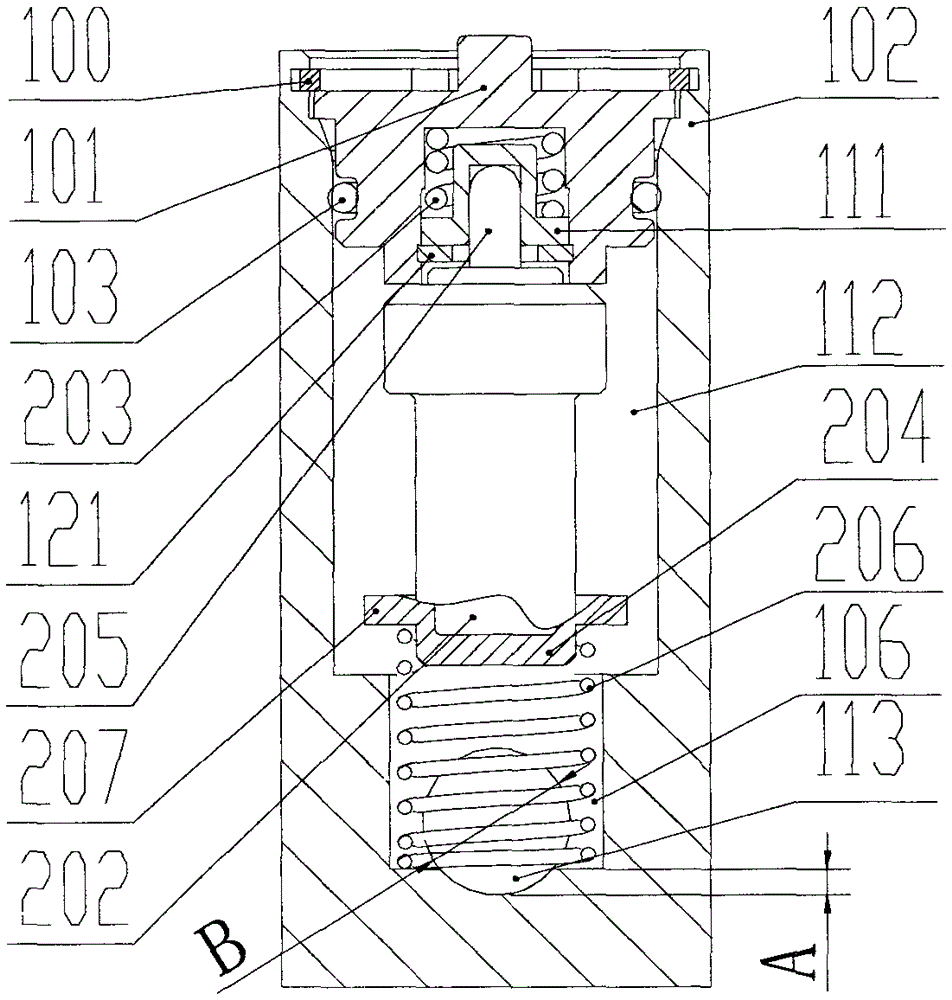
[0037] The initial deformation force of the first spring 203 in the present invention means that when the first spring 203 is compressed and deformed by the pressure of the push rod 205 so that the retaining ring 121 no longer bears the pressure exerted by the first spring 203, the first spring 203 under pressure.

[0038] The above definitions are applicable in all statements herein, and will not be repeated hereafter.

[0039] There are many ways to implement the specific thermostat, such as Figure 1-Figure 10 As shown, in various thermostat embodiments of the present invention: the thermostat includes a valve body 102 provided with a cavity 112 and a thermodynamic element fitted in the cavity 112, and the thermodynamic element includes a thermal sensor The bod...

Embodiment 1

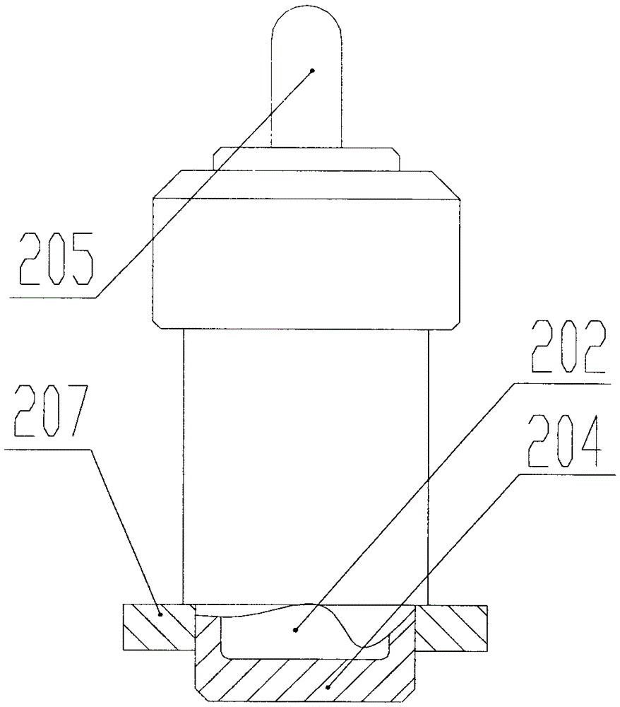
[0054] The difference between Embodiment 1 and Embodiments 2, 3, 4, and 5 lies in the position of the cover 207. As the distance between the cover and the second end of the body is different, the structural design requirements of the thermostat change accordingly. The cover 207 and the main body 204 are fixedly connected, and may also be an integral structure.

[0055] The second spring 206 can be in contact with the cover 207, the outer diameter of the end of the body 204 close to the third interface 106 is smaller than the inner diameter of the third interface 106, one end of the second spring 206 is in pressing contact with the cover 207, and the other end is in contact with the cover 207. The inner wall of the valve body 102 is press-contacted.

[0056] It can also directly abut against the second end of the body 204 , one end of the second spring 206 is in pressure contact with the end of the body 204 , and the other end is in pressure contact with the inner wall of the v...

Embodiment 5

[0060] The difference between Embodiment 5 and other embodiments is that a flow channel communicating with the third interface 106 is provided in the valve body of the thermostats of Embodiments 1-4. However, the third interface 106 of the thermostat valve body in Embodiment 5 needs to be externally connected to pipes connected to other devices.


PUM


Abstract

The invention relates to a thermostat for a heat exchange loop. One end of an end cover is provided with an opening, and the opening end of the end cover is arranged towards the interior of a cavity; the opening end of the end cover is provided with a check ring which is fixedly arranged; the end cover is internally provided with a first spring which is in a compressed state; a fixedly connected seal cover is arranged at the peripheral side of a body of a thermal actuator; the outer diameter of the seal cover is larger than the inner diameter of a third interface; a valve body is also internally provided with a second spring which is in a compressed state; the second spring is arranged between the thermal actuator and the inner wall of the valve body; the initial deformation force of the first spring is larger the pressure applied to the second spring when the third interface is sealed by the seal cover; when the thermal actuator is heated, the body moves downwards, and the seal cover is driven to move until sealing the third interface; after the third interface is sealed, the force generated by the thermal expansion of thermosensitive material of the thermal actuator is not enough for pushing the first spring to be continuously compressed until the thermosensitive material is completely expanded.

Description

technical field [0001] The invention relates to the mechanical field, and more specifically, relates to a thermostat for a heat exchange circuit. Background technique [0002] During the driving process of the car, lubricating oil needs to be replenished in time to ensure the normal operation of the car. If the lubrication performance of the lubricating oil is not good enough, it will greatly reduce the service life of the car and even cause a car accident. The lubricating performance of lubricating oil is closely related to its own temperature. When the temperature of lubricating oil is too high or too low, the lubricating oil will lose its lubricating performance. [0003] The temperature of the lubricating oil is generally not too high during normal driving. When the vehicle is overloaded or the four-wheel drive mode is set to drive on snow or off-road, the vehicle is driving under the condition of excessive slippage of the hydraulic torque converter, which may cause gea...

Claims


Application Information

Patent Timeline
Patent Type & Authority Patents(China)
IPC IPC(8): F16H57/04F16K31/68F16K27/12F16K11/044
CPCF16H57/0415
Inventor 裘浩明尹斌王晖潘涛
Owner ZHEJIANG SANHUA AUTOMOTIVE COMPONENTS CO LTD
Learn More