A single-drive multi-joint body of a quadruped robot
A quadruped robot and multi-joint technology, applied in the field of robotics, can solve problems such as poor flexibility of movement and lack of bionics, and achieve the effect of improving mobility
- Summary
- Abstract
- Description
- Claims
- Application Information
AI Technical Summary
Problems solved by technology
Method used
Image


Examples
Embodiment 1
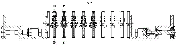
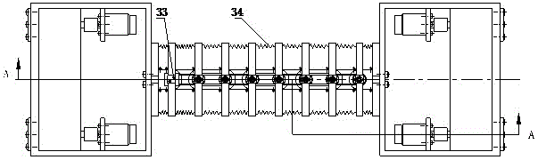
[0022] Such as figure 1 As shown, the single-drive multi-joint body of the quadruped robot of the present invention includes a multi-joint body (II), and the front and rear ends of the multi-joint body (II) are respectively connected with the front body (I) and the rear body (III). The four legs are symmetrically arranged at the four ends of the front body (I) and the rear body (III), and it is characterized in that the multi-joint body (II) is composed of several joints, including a single motor drive mechanism at the front end ( A), multiple synchronous toothed belt transmission mechanisms (B), multiple linkage mechanisms (C) and multiple annular support mechanisms (D); the single motor drive mechanism (A) and the synchronous toothed belt mechanism ( B) The transmission is connected through the link mechanism (C) and flexibly connected by the ring support mechanism (D).
Embodiment 2
[0024] see figure 1 , figure 2 , image 3 , Figure 4 , Figure 5 , Figure 6 , this embodiment is basically the same as Embodiment 1, and the special features are:
[0025] The multi-joint body of the single-drive quadruped bionic robot is characterized in that the single-motor drive mechanism (A) includes: motor (1), motor support (21), bolt 1 (2), bolt 2 ( 31), support ring 1 (22), support frame 1 (23), coupling (3), shaft 1 (6), shaft 2 (12), connecting rod 1 (8) and connecting rod 2 (10). The motor (1) body is connected to the motor support (21) through bolt 1 (2), and the motor support (21) and support ring 1 (22) are connected through bolt 2 (31). The support ring 1 (22) is connected with the connecting rod 1 (8) through the support frame 1 (23). The coupling (3) connects the shaft of the motor (1) to the shaft 1 (6). Shaft 1 (6) is threaded to shaft 2 (12). Shaft 1 (6) and connecting rod 1 (8) are connected through deep groove ball bearing 1 (7), so that shaf...
PUM
 Abstract
Description
Claims
Application Information
 - R&D
- Intellectual Property
- Life Sciences
- Materials
- Tech Scout
- Unparalleled Data Quality
- Higher Quality Content
- 60% Fewer Hallucinations
Browse by: Latest US Patents, China's latest patents, Technical Efficacy Thesaurus, Application Domain, Technology Topic, Popular Technical Reports.
© 2025 PatSnap. All rights reserved.Legal|Privacy policy|Modern Slavery Act Transparency Statement|Sitemap|About US| Contact US: help@patsnap.com