
Displaying apparatus that can switch mirror mode and display mode

A display device and display mode technology, applied in nonlinear optics, instruments, optics, etc., can solve the problems of display image interference, poor visual effect, inability to freely set the display to display mirror images, etc., to improve the interference phenomenon. Effect

Active Publication Date: 2014-02-05
AU OPTRONICS CORP
View PDF5 Cites 16 Cited by
  • Summary
  • Abstract
  • Description
  • Claims
  • Application Information

AI Technical Summary

Problems solved by technology

In this technology, the mirror image often interferes with the displayed image, resulting in poor visual effects
In addition, the user cannot freely set a certain area on the display to display a mirror image while allowing another area to display a display image

Method used

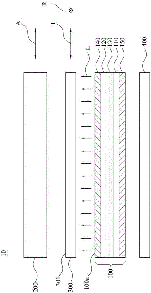
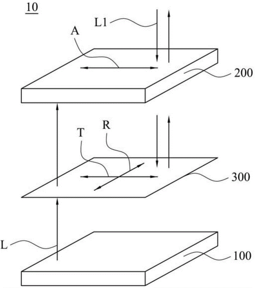
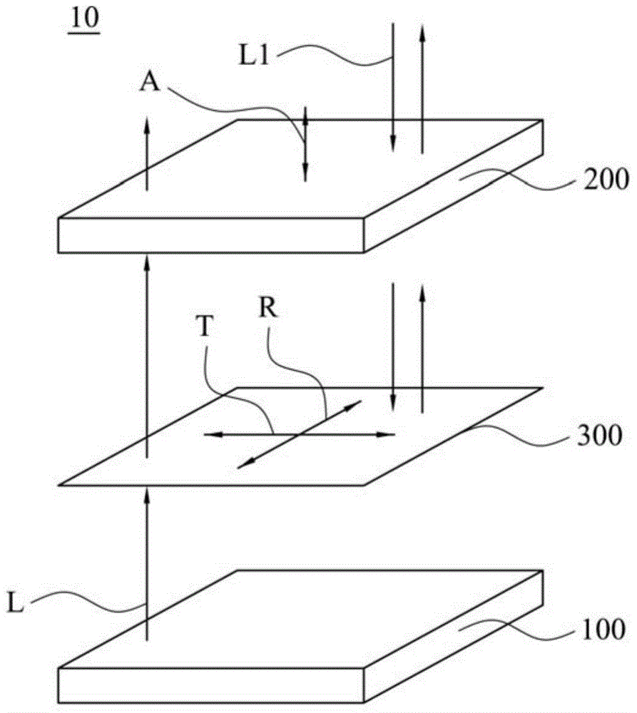

Image

  • Displaying apparatus that can switch mirror mode and display mode
  • Displaying apparatus that can switch mirror mode and display mode
  • Displaying apparatus that can switch mirror mode and display mode

Examples


Embodiment Construction

[0070] In order to make the description of the present disclosure more detailed and complete, the following provides an illustrative description of the implementation aspects and specific embodiments of the present invention; but this is not the only form of implementing or using the specific embodiments of the present invention. The various embodiments disclosed below can be combined or replaced with each other when beneficial, and other embodiments can also be added to one embodiment, without further description or illustration.

[0071] In the following description, numerous specific details will be set forth in order to enable readers to fully understand the following embodiments. However, embodiments of the invention may be practiced without these specific details. In other instances, well-known structures and devices are only schematically shown in order to simplify the drawings.

[0072] An aspect of the present invention is to provide a display device capable of switchi...


PUM


Abstract

A displaying apparatus that can switch mirror mode and display mode, comprises a displaying panel, a polarization component and a reflective polaroid, wherein the displaying panel has an outlet surface that reflects light in polarized direction; the polarization component has an absorbing shaft on one side of the outlet surface; and the polarization component also has a switchable polarization mode and a non-polarized mode. When in polarization mode, the polarization component absorbs polarized directional light that is parallel to the absorbing shaft; when in non-polarized mode, the polarization component allows light in polarized direction reflected by the displaying panel pass by. The reflective polaroid is set between the displaying panel and the polarization component.

Description

technical field [0001] The present invention relates to a display device, and in particular to a display device capable of switching between a mirror mode and a display mode. Background technique [0002] In recent years, as the fields of application of flat panel displays have expanded, the demand for displays with a mirror conversion function has also increased. The so-called "display with mirror conversion function" usually means that the display can have both the display function and the mirror function. In the prior art, a reflective polarizer is usually added to the display to form a display with a mirror effect. In this technique, the mirror image often interferes with the display image, resulting in poor visual effects. In addition, the user cannot freely set a certain area on the display to display a mirror image while allowing another area to display a display image. In view of this, there is an urgent need for an improved display that can improve the above-ment...

Claims


Application Information

Patent Timeline
Patent Type & Authority Applications(China)
IPC IPC(8): G02F1/1335
CPCG02F1/133536G02F1/13725G02F2203/01G02F2203/02
Inventor 陈奎百李家豪廖烝贤薛芷苓
Owner AU OPTRONICS CORP
Learn More