
External separation and reunion device for electronic lock

A clutch device, electronic lock technology, applied in construction locks, non-mechanical transmission-operated locks, buildings, etc., can solve the limitation of structural space, the design space of the driving mechanism for driving the clutch device, and the impact on product reliability and maintainability. and other problems, to achieve the effect of convenient use and simple structure

Inactive Publication Date: 2014-02-05
SHANGHAI MYTEC DIGITAL
View PDF7 Cites 3 Cited by
  • Summary
  • Abstract
  • Description
  • Claims
  • Application Information

AI Technical Summary

Problems solved by technology

[0003] At present, most of the clutch devices used in electronic locks are built into the lock body. Since the lock body is installed inside the door panel, the structural space is limited, which leads to a great limitation in the design space of the driving mechanism for driving the clutch device, which seriously affects the reliability and maintenance of the product. sex
Some manufacturers place the clutch device of the electronic lock in the outer protective cover of the electronic lock, which increases the design space, but because the clutch device is a safety component, placing it in the outer protective cover of the electronic lock greatly reduces the safety of the electronic lock. safety

Method used


Image

  • External separation and reunion device for electronic lock
  • External separation and reunion device for electronic lock
  • External separation and reunion device for electronic lock

Examples


Embodiment Construction

[0024] The technical solutions of the present invention will be further explained below in conjunction with the drawings and embodiments, but the following content is not intended to limit the protection scope of the present invention.

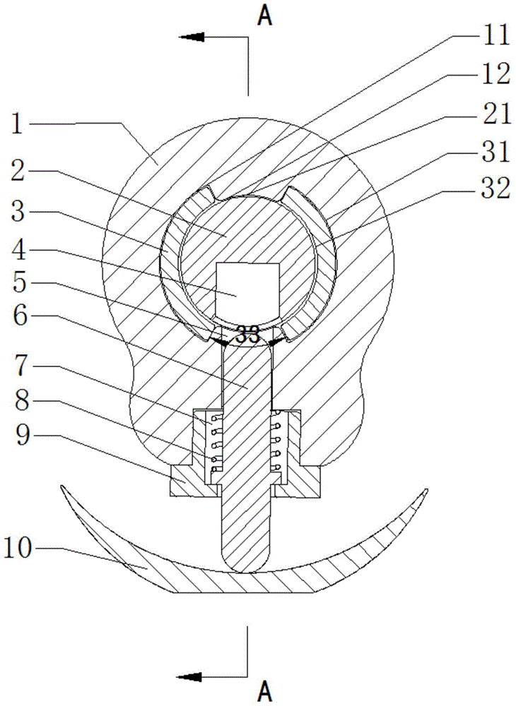
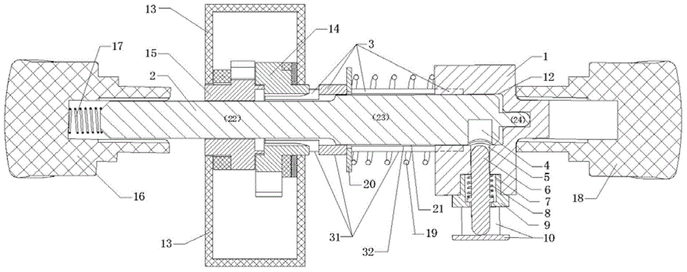
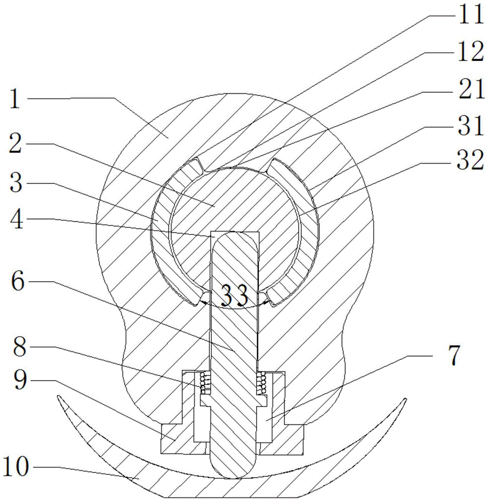
[0025] Such as figure 1 , figure 2 As shown, this embodiment provides an external clutch device for an electronic lock, which includes a clutch body 1, an outer handle shaft 2 and an inner handle shaft 3, and the outer handle shaft 2 and the inner handle shaft 3 are coaxial. The outer arc surface 31 of the inner handle shaft matches the outer arc surface 11 of the clutch body, the inner arc surface 32 of the inner handle shaft matches the outer arc surface 21 of the outer handle shaft, and the outer arc surface 21 of the outer handle shaft matches the inner arc surface 12 of the clutch body. Matching; the outer handle rotating shaft 2 can rotate relative to the clutch main body 1 and the inner handle rotating shaft 3 .

[0026] In this embo...


PUM


Abstract

The invention discloses an external separation and reunion device for an electronic lock. The external separation and reunion device comprises a separation and reunion main body, an outer handle revolving shaft and an inner handle revolving shaft, wherein the outer handle revolving shaft comprises a square shaft part, a circular shaft part and a thimble part; the end part of the square shaft part of the outer handle revolving shaft is connected with an outer handle, and is provided with an outer shaft spring; the outer handle revolving shaft is crimped inside the separation and reunion main body through the outer shaft spring; the square shaft part of the outer handle revolving shaft is arranged on a lock body by passing through an inner lock core rotor and an outer lock core rotor; the inner handle revolving shaft is spliced in the separation and reunion main body, and is crimped on the inner lock core rotor of the lock body by using an inner shaft gasket through an inner shaft spring, so that the external separation and reunion device is always connected with the inner lock core rotor; a cylindrical through hole is formed in the center of the inner handle revolving shaft; the inner handle revolving shaft is directly sleeved outside the circular shaft part of the outer handle revolving shaft. The external separation and reunion device has the advantages of simple structure, convenience in use, low production cost and easiness in maintenance.

Description

technical field [0001] The invention relates to an electronic lock, in particular to an external clutch device of the electronic lock. Background technique [0002] In the prior art, the clutch devices of electronic locks used by people are various. Generally, the clutch devices of electronic locks include a casing, a handle shaft and a lock cylinder shaft. The handle shaft and the lock cylinder shaft are arranged in the inner rotation hole of the casing. The inner rotating hole, the handle shaft and the lock cylinder shaft are concentric; the outer arc surface of the handle shaft matches the inner ring of the housing, and the inner arc surface of the handle shaft matches the lock cylinder shaft; the handle shaft can be opposite to the housing, the lock cylinder shaft Rotate, when the handle shaft and the lock cylinder shaft are in a linked state, the handle shaft can drive the lock cylinder shaft to rotate together. The rotating shaft of the lock core is provided with a li...

Claims


Application Information

Patent Timeline
IPC IPC(8): E05B15/00E05B47/00
Inventor 詹万泉黄立严吴凌峰
Owner SHANGHAI MYTEC DIGITAL
Learn More