
An Air Chamber Structure for Reducing Vacuum Absorbing Negative Pressure Fluctuation of Rotor Spinning Machine

A rotor spinning machine and air chamber technology, which is applied to spinning machines, open-end spinning machines, continuous winding spinning machines, etc., can solve the problem that the yarn quality is greatly affected and the space available for the miscellaneous box Small size, high frequency of manual removal of impurities, etc., to achieve the effect of simple and reliable structure, prolonging coverage time and reducing labor intensity

Inactive Publication Date: 2015-10-21
上海捷春进出口贸易有限公司
View PDF6 Cites 0 Cited by
  • Summary
  • Abstract
  • Description
  • Claims
  • Application Information

AI Technical Summary

Problems solved by technology

The fluctuation of negative pressure has great influence on yarn quality
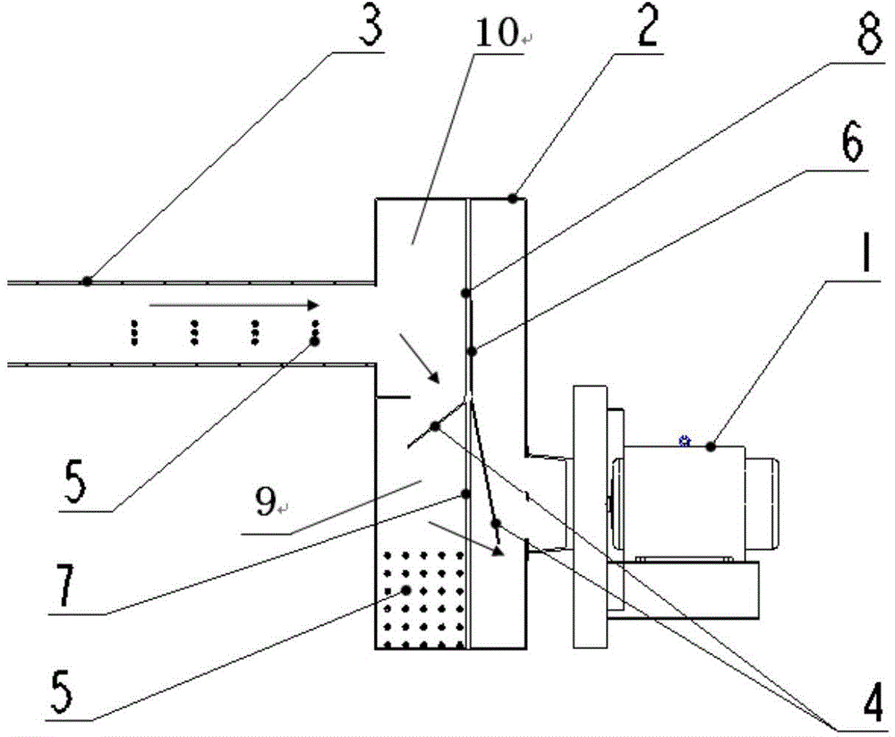
[0009] 4. Since a conversion channel needs to be reserved in the upper part of the air chamber, and the height of the miscellaneous box is limited by the space of the machine, and the depth is limited by the length of the arm when manually removing impurities, the usable space of the miscellaneous box is relatively small, and manual removal of impurities high frequency

Method used


Image

  • An Air Chamber Structure for Reducing Vacuum Absorbing Negative Pressure Fluctuation of Rotor Spinning Machine
  • An Air Chamber Structure for Reducing Vacuum Absorbing Negative Pressure Fluctuation of Rotor Spinning Machine
  • An Air Chamber Structure for Reducing Vacuum Absorbing Negative Pressure Fluctuation of Rotor Spinning Machine

Examples


Embodiment Construction

[0037] Below in conjunction with accompanying drawing and embodiment, the present invention is described in further detail:

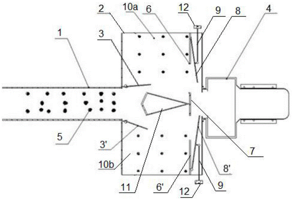
[0038] combine image 3 As shown, an air chamber structure for reducing the fluctuation of the miscellaneous suction negative pressure of a rotor spinning machine includes an air chamber 2, the front end of the air chamber communicates with the miscellaneous suction duct 1, and the rear end of the air chamber communicates with the miscellaneous suction pipe 1. The fans are connected in 4 phases,

[0039] The air chamber is fixedly equipped with a left filter screen 6, a right filter screen 6' and a middle partition 7, and the left filter screen and the right filter screen are fixedly connected to the left and right side walls of the air chamber respectively, and the middle part The clapboard is located between the left filter screen and the right filter screen, facing the miscellaneous air duct. The left, right filter screen and the middle partition di...


PUM

PropertyMeasurementUnit
lengthaaaaaaaaaa

Abstract

The invention relates to an air compartment structure capable of reducing negative-pressure fluctuation of impurity suction of a rotor spinning machine. The air compartment structure comprises an air compartment, the front end of the air compartment is connected with an impurity suction air pipe, the rear end of the air compartment is connected with an impurity suction fan, a left filter screen, a right filter screen and a middle partition are fixedly mounted in the air compartment and divide the same into a front portion and a rear portion, and a front half portion of the air compartment is an impurity collection box. The front side face of the middle partition is fixedly connected with a separator, a left filter screen partition and a right filter screen partition are hinged to the left end and the right end of each filter screen, connecting rods are hinged to the middles of the left filter screen partitions and the right filter screen partitions, and the other end of each connecting rod penetrates out of the side wall of the air compartment and is provided with a handle. The air compartment structure is beneficial to impurity deposition, and covered time of the filter screens is prolonged. When an air duct is switched, change of ventilation area is only one half of that of the structure in the prior art, negative-pressure fluctuation is reduced by one half correspondingly, and yarn quality is improved beneficially.

Description

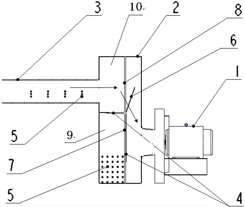
technical field [0001] The invention relates to an air chamber structure of a rotor spinning machine, in particular to an air chamber structure for reducing the fluctuation of the miscellaneous suction negative pressure of the rotor spinning machine, and belongs to the technical field of spinning equipment. Background technique [0002] At present, in the air suction type rotor spinning machine that actively absorbs impurities, the impurities in the carding cavity are removed by a suction fan. The filter screen isolates and collects impurities. The air chamber is equipped with a conversion channel. Before removing impurities, switch the miscellaneous suction air duct to the conversion channel, so that the miscellaneous suction air duct is isolated from the miscellaneous box, and then switch to the working state after the impurities are removed. [0003] Such as figure 1 Shown: the air chamber of the prior art is vertically installed with a main filter screen 7 and a second...

Claims


Application Information

Patent Timeline
Patent Type & Authority Patents(China)
IPC IPC(8): D01H4/36
Inventor 李显彪王旭纯
Owner 上海捷春进出口贸易有限公司
Learn More