Truck vibration energy recovery system

A vibration energy recovery and truck technology, applied in vehicle components, auxiliary drive devices, control devices, etc., can solve the problems of low energy recovery efficiency, poor reliability, and inability to achieve high-efficiency recovery of vibration energy, and improve the reliability of use. performance and energy recovery efficiency, avoid poor reliability, and avoid the effects of low energy recovery efficiency

Active Publication Date: 2014-02-05
CHINA FIRST AUTOMOBILE
View PDF5 Cites 14 Cited by
  • Summary
  • Abstract
  • Description
  • Claims
  • Application Information

AI Technical Summary

Problems solved by technology

[0003] At present, the vibration energy recovery system of trucks is generally installed between the frame and the axle, and there are mainly two specific implementation forms: one is to directly place the energy-feeding compression cylinder vertically, such as a cylinder that can store energy during compression Or hydraulic cylinders, etc., due to the small dynamic deflection of the suspension during the actual use of the truck, the energy recovery efficiency is very low, and the practicability is very poor. At the same time, the auxiliary parts are more complicated and the cost is higher; another realization form The energy-feeding compression cylinder is placed along the longitudinal direction of the frame, and the conversion of the motion form is realized through the rack and pinion mechanism installed between the frame and the axle. Since the axle has six degrees of freedom in the actual application process, the gear teeth Bars often break off, resulting in failure of the energy recovery system, and this form of implementation is less reliable
[0004] Moreover, the existing vibration energy recovery system for trucks is difficult to recover high-frequency and small-amplitude vibrations, and the large-amplitude vibrations are less, resulting in low energy recovery efficiency, which cannot meet the requirements of high-efficiency recovery of vibration energy. Some truck vibration energy recovery systems are difficult to promote
In addition, a mature vibration energy recovery system has not yet appeared in the field of trucks

Method used


Image

  • Truck vibration energy recovery system
  • Truck vibration energy recovery system
  • Truck vibration energy recovery system

Examples


Embodiment

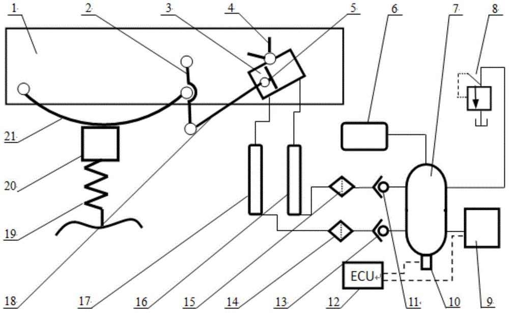
[0069] Next, a certain medium-sized truck produced by a certain automobile company is taken as a prototype vehicle to further illustrate the truck vibration energy recovery system of the present invention.

[0070] The overall structure of the truck vibration energy recovery system of the prototype vehicle is as described above. Wherein, the length of the gas storage tank 7 in the prototype vehicle is 500 mm, and the diameter is 250 mm.

[0071] In order to solve the problem of low energy recovery efficiency caused by high-frequency and small-amplitude vibration in the existing truck vibration energy recovery system, which is difficult to establish working pressure and less large-amplitude vibration, the present invention improves the original enlarged lifting lug of the leaf spring ( Length 110mm) is redesigned, according to the strength of the increased lifting lug material and the installation space, the length of the original increased lifting lug is doubled, and the lengt...


PUM


Abstract

The invention discloses a truck vibration energy recovery system. The truck vibration energy recovery system comprises a leaf spring, an enlarged lifting lug, a connecting rod mechanism, a double-acting air cylinder and an air storage tank which are sequentially connected, wherein one end of the leaf spring is connected to a frame, and the other end of the leaf spring is connected to the enlarged lifting lug; one end of the enlarged lug is connected to the frame through a revolute pair, and the other end of the enlarged lug is connected with the connecting rod mechanism through a revolution pair; and an air cylinder piston in the double-acting air cylinder is connected with the connecting rod mechanism. According to the truck vibration energy recovery system, the working stroke is enlarged through the enlarged lifting lug, the switching of motion forms is realized through the unique motion trail of the enlarged lifting lug and the connecting rod mechanism, the using reliability and the energy recovery efficiency are improved, and the problems of low energy recovery efficiency and complex structure due to vertical arrangement of an energy feedback type cylinder as well as poor reliability due to longitudinal arrangement of the energy feedback type cylinder are solved.

Description

technical field [0001] The invention belongs to the field of energy recovery of trucks, and in particular relates to a vibration energy recovery system of trucks. Background technique [0002] Economy is one of the important indicators for evaluating vehicle performance. At present, all automobile manufacturers are pursuing low fuel consumption, and energy recovery has opened up a new and effective way to reduce fuel consumption and improve economy. In the context of the international economic crisis and domestic fuel tax reform, it is of great significance to recover vehicle vibration energy and use it in energy-consuming systems to improve fuel economy. [0003] At present, the vibration energy recovery system of trucks is generally installed between the frame and the axle, and there are mainly two specific implementation forms: one is to directly place the energy-feeding compression cylinder vertically, such as a cylinder that can store energy during compression Or hydr...

Claims


Application Information

Patent Timeline
IPC IPC(8): B60K25/10
Inventor 赵雷雷李胜王娜黄德惠胡金蕊李栋宋乃华
Owner CHINA FIRST AUTOMOBILE
Why Eureka
Try Eureka