
Constant-current static-pressure rolling composite guide rail and automatic centering technological worktable

An automatic centering and worktable technology, applied in metal processing equipment, metal processing mechanical parts, manufacturing tools, etc., can solve the problems of lack of key design theory and technology, worktable running swaying, low processing accuracy, etc., to overcome Unstable centering, uniform film floating, and small film fluctuations

Inactive Publication Date: 2014-02-05
大连飞达重型机床制造有限公司
View PDF9 Cites 2 Cited by
  • Summary
  • Abstract
  • Description
  • Claims
  • Application Information

AI Technical Summary

Problems solved by technology

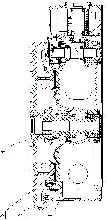
In our country, there are many single-column and double-column CNC vertical lathes produced by many manufacturers, which are modified from the structure of the original ordinary vertical lathe. For the design of the guide rail structure of this workbench, see figure 1 , mainly composed of workbench 2, workbench base 1, guide rail plate 3, spindle 4, two sets of double-row radial short cylindrical roller bearings (taper 1:12) are used for centering support in the radial direction, and the guide rail adopts dynamic pressure and static pressure Or the way of dynamic and static pressure guide rail, the main shaft adopts the long main shaft structure. This design method lacks key design theory and technology, and its defects are prominently manifested in: the workbench has no preload. There is a phenomenon of shaking the head during operation, so that the workpiece has defects such as wavy lines and low machining accuracy (up to IT8 level)

Method used


Image

  • Constant-current static-pressure rolling composite guide rail and automatic centering technological worktable
  • Constant-current static-pressure rolling composite guide rail and automatic centering technological worktable
  • Constant-current static-pressure rolling composite guide rail and automatic centering technological worktable

Examples


Embodiment Construction

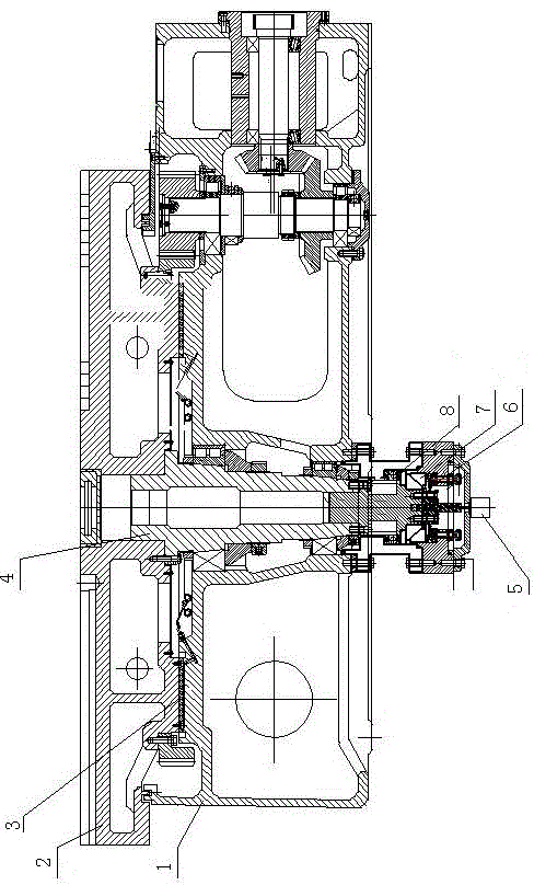
[0012] The structure of the constant-current static pressure rolling-sliding composite guide rail plus automatic centering technology workbench of the present invention is as follows: figure 2 As shown, there is a workbench 2 on the workbench base 1, the main shaft 4 is located in the middle of the workbench base 1 and the workbench 2, a guide rail plate 3 is provided between the workbench base 1 and the workbench 2, and a set of A one-way thrust ball bearing 8 and a set of thrust joint bearings 7 that automatically center the main shaft of the workbench. This structure still maintains the original main shaft structure. Two sets of double-row radial short cylindrical roller bearings (taper 1:12) are used for centering support in the radial direction. A set of one-way thrust ball bearings is added to the lower part of the main shaft. , and added a set of joint bearings 7 to automatically center the table spindle 1, and designed a disc spring 6 to adjust the preload of the guid...


PUM


Abstract

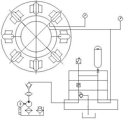
The invention relates to a constant-current static-pressure rolling composite guide rail and automatic centering technological worktable. A worktable base is provided with a worktable, a main shaft is arranged in the middle part of the worktable base and the worktable, a guide rail plate is arranged between the worktable base and the worktable, and the lower part of the main shaft is provided with a set of single-direction thrusting ball bearing and a set of thrusting joint bearing facilitating the automatic centering of the main shaft of the worktable. By adequately utilizing the rolling composite guide rail technology, the preload constant-current (constant-voltage) static-pressure film floating technology and the automatic centering technology, the weight of the worktable and a workpiece can be overcome by the constant-current static-pressure supporting force of the main guide rail, the floating gap of the main guide rail is limited by a rolling pair guide rail, an uniform oil membrane is generated among friction surfaces of the main guide rail, the oil membrane has certain rigidness, the guide rail has double advantages of a static-pressure guide rail and a rolling guide rail and has the advantages such as heavy load, large rigidness, high stability, uniformity in film floatation, small fluctuation of a film and the like; and the automatic centering technology overcomes the weakness that the original worktable is unstable to center.

Description

technical field [0001] The invention relates to the technical field of numerical control machining, in particular to a workbench structure of a numerical control vertical lathe. Background technique [0002] CNC vertical lathe worktable and spindle structure are one of the most critical functional components of CNC machine tools. The design and manufacture of its structure directly affect the performance and precision of CNC machine tools. In our country, there are many single-column and double-column CNC vertical lathes produced by many manufacturers, which are modified from the structure of the original ordinary vertical lathe. For the design of the guide rail structure of this workbench, see figure 1 , mainly composed of workbench 2, workbench base 1, guide rail plate 3, spindle 4, two sets of double-row radial short cylindrical roller bearings (taper 1:12) are used for centering support in the radial direction, and the guide rail adopts dynamic pressure and static p...

Claims


Application Information

Patent Timeline
Patent Type & Authority Applications(China)
IPC IPC(8): B23Q1/38B23Q1/25
CPCB23Q1/38B23Q1/017B23Q1/26
Inventor 朱学峰
Owner 大连飞达重型机床制造有限公司
Learn More