
Light emitting device and method for manufacturing same

A light-emitting device and manufacturing method technology, applied in the direction of electrical components, electric solid-state devices, circuits, etc., can solve the problems of lack of important characteristics of environmental protection lighting, etc.

Inactive Publication Date: 2014-01-22
ELM CO LTD
View PDF6 Cites 26 Cited by
  • Summary
  • Abstract
  • Description
  • Claims
  • Application Information

AI Technical Summary

Problems solved by technology

However, the light emitting device 147 of this configuration lacks important characteristics required for environmentally friendly lighting.

Method used


Image

  • Light emitting device and method for manufacturing same
  • Light emitting device and method for manufacturing same
  • Light emitting device and method for manufacturing same

Examples


Embodiment Construction

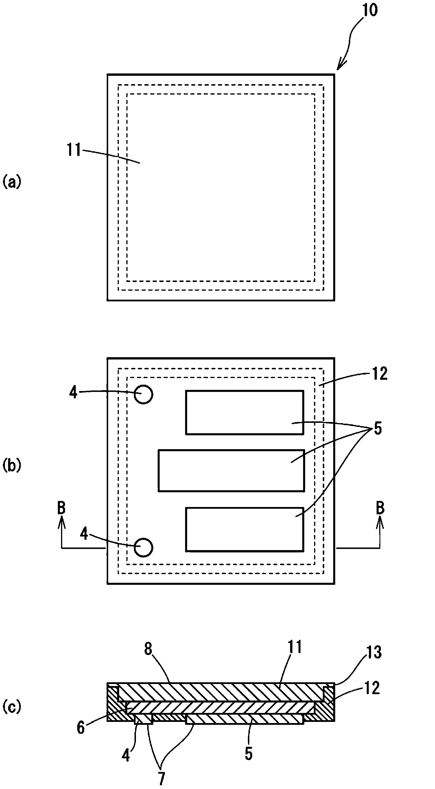
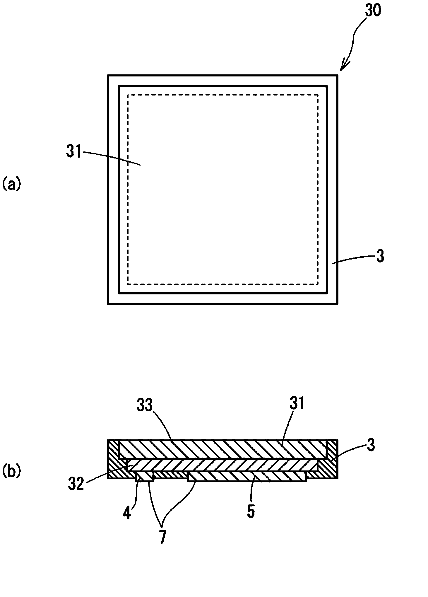
[0079] Hereinafter, embodiments of the light-emitting device and its manufacturing method of the present invention will be described in detail in order of the first to seventh embodiments with reference to the drawings.

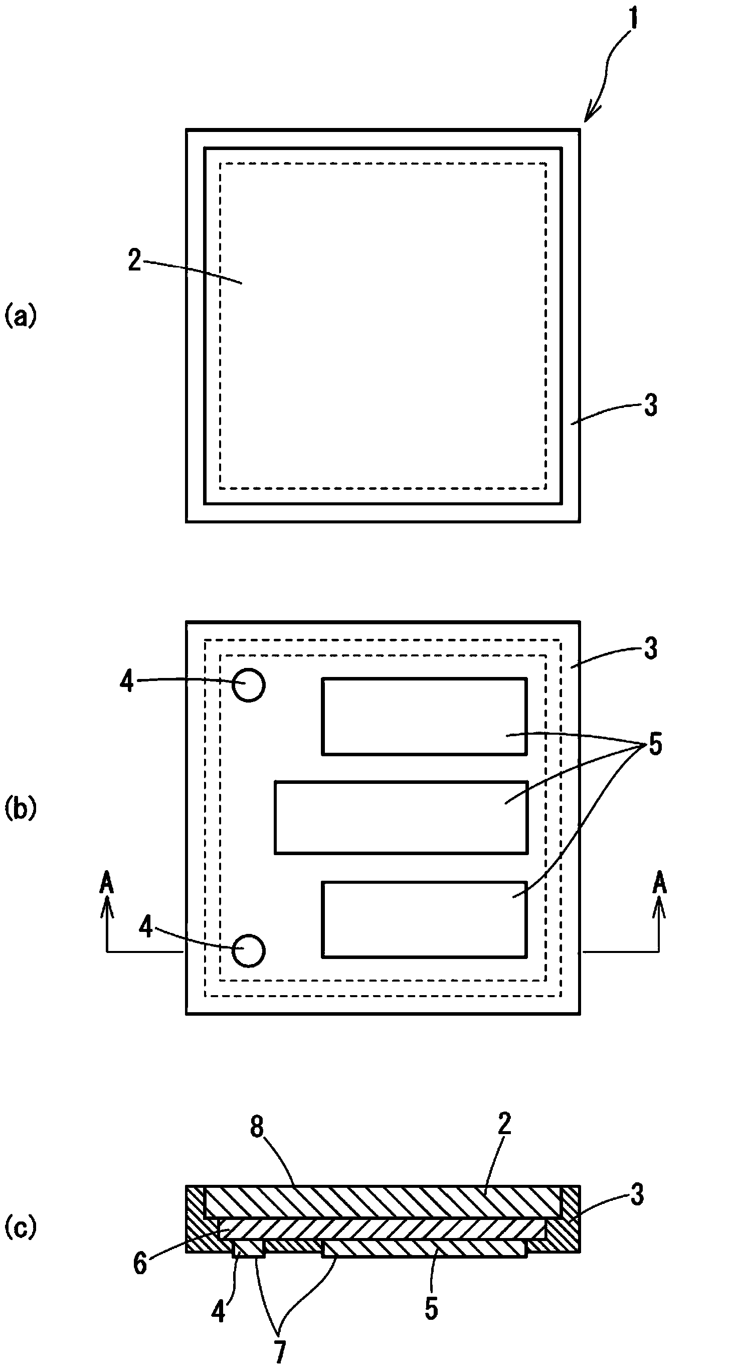
[0080] first, figure 1 The light emitting device of the first embodiment is shown. In addition, its manufacturing method such as Figure 5 As shown, it consists of steps (a) to (f), and is a manufacturing method for collectively manufacturing a plurality of light emitting devices 1 .

[0081] At this time, the light emitting device 1 such as figure 1 As shown, it is composed of a semiconductor light-emitting element 6, a phosphor-containing film 2 and a reflective wall 3. The semiconductor light-emitting element 6 is formed with a thickness of 15 μm on the n-side electrode and p-side electrode of the blue LED element emitting blue light. The elements of protrusions 4 and 5, the phosphor-containing film 2 contains phosphor, and is integrally formed on the...


PUM


Abstract

Provided are light emitting device having low cost and excellent characteristics, and a method for manufacturing the light emitting device. In the present invention, a chip-sized package having a reflecting wall is formed by forming a double structural body wherein a fluorescent material-containing film piece (2) is bonded on a light extraction surface of a semiconductor light emitting element (6) having bumps (4, 5) on an electrode-forming surface, and by covering, with a reflecting wall (3), double structural body exposed surfaces other than the bump-mounted surface (7) and the light output surface (8) of the double structural body. Consequently, a light emitting device having low cost without requiring a package substrate, and excellent luminance characteristics and heat dissipating characteristics, and a manufacturing method having excellent chromaticity yield can be provided.

Description

technical field [0001] The present invention relates to a light-emitting device used for LED lighting and a manufacturing method thereof, and particularly to a light-emitting device and a manufacturing method thereof, that is, the light-emitting device is composed of a semiconductor light-emitting element emitting blue light, purple light, or ultraviolet light, It is composed of a phosphor layer that converts this light into white light, and a reflective wall that efficiently reflects white light in a certain direction. Background technique [0002] In recent years, lighting devices using LEDs have been put into practical use and are gradually replacing incandescent lamps and fluorescent lamps. The reason for this is that it is a flagship eco-friendly product that can significantly reduce carbon dioxide emissions that cause global warming because it consumes less power and can obtain the same brightness. For example, a 9W LED lamp can be used to achieve the same brightness ...

Claims


Application Information

Patent Timeline
Patent Type & Authority Applications(China)
IPC IPC(8): H01L33/50H01L33/54
CPCH01L33/46H01L33/486H01L33/505H01L2224/48091H01L2224/48465H01L2924/00014H01L2924/00H01L2924/181H01L33/56H01L2924/00012H01L33/50H01L33/54H01L33/60H01L22/12H01L33/10
Inventor 井上登美夫宫原隆和
Owner ELM CO LTD
Learn More