LTD module and synchronous trigger method thereof

A circular direction and branch technology, which is applied to the LTD module and its synchronous trigger field, can solve the problems of the large and complex trigger pulse generation system of the trigger circuit topology structure, and cannot be used as a LTD branch switch, etc., to improve the trigger reliability and simplify the requirements. Effect

Active Publication Date: 2014-01-08
NORTHWEST INST OF NUCLEAR TECH
View PDF4 Cites 7 Cited by
  • Summary
  • Abstract
  • Description
  • Claims
  • Application Information

AI Technical Summary

Problems solved by technology

Both at home and abroad are actively exploring and researching the new trigger circuit topology and trigger mode of the LTD-type drive source, such as the literature (F.J.Zutavern, S.F.Glover, K.W.Reed, et al.PCSS triggered pulsed power switches[C] / / 16th IEEE Int Pulsed Power Conf.2007:231-235.) studied the feasibility of the photoconductive switch triggering the LTD gas switch. Due to the limitation of the operating voltage and flow capacity of the photoconductive switch, it cannot be used as an LTD branch switch, but can only be used as the pre-stage of the LTD trigger system Trigger switch; literature (Yin Jiahui, Wei Hao, Sun Fengju, etc. Synchronous trigger system driven by fast pulse linear transformer[J]. Strong Laser and Particle Beam, 2012,24(4):871-875.(Yin Jiahui,Wei Hao, Sun Fengju, et al. Experimental research of high-power spark gap switch. High Power Laser and Particle Beams, 2012, 24(4): 871-875; Lei Yu, Qiu Jian, Liu Kefu. Synchronous triggering of linear transformer drive source multi-channel switch Technology [J]. High Power Laser and Particle Beam, 2012,24(4):765-770.(Lei yu, Qiu Jian, Liu kefu, et al.Multi-output synchronization trigger for linear transformer driver.High Power Laser and Particle Beams, 2012, 24 (4): 765-770) discussed the topology of the multi-stage series LTD trigger circuit and the generation of multi-channel fast leading edge and voltage 140kV trigger pulses, but each 1MA LTD module still needs to apply 4 channels For a trigger pulse with a fast leading edge amplitude of 140kV, the topology of the trigger circuit and the trigger pulse generation system are still huge and complex

Method used


Image

  • LTD module and synchronous trigger method thereof
  • LTD module and synchronous trigger method thereof
  • LTD module and synchronous trigger method thereof

Examples


Embodiment Construction
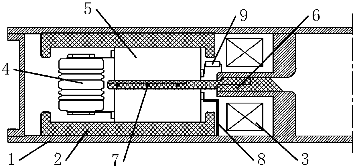
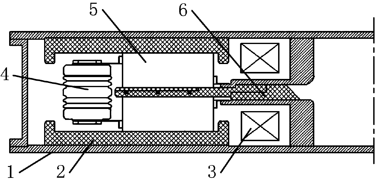
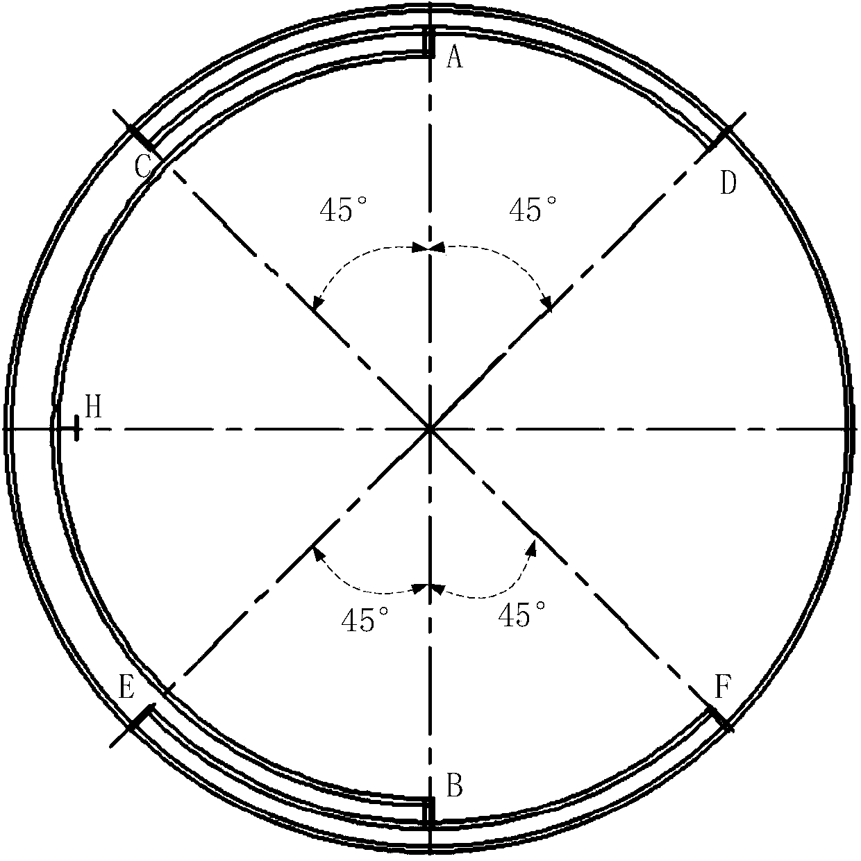
[0030] The core idea of ​​the present invention is to introduce a fast leading-edge trigger pulse and use a branch placed inside the LTD module. One end of the branch is grounded, and the other end is connected to the secondary external of the coupled magnetic core through a high-resistance load formed by a spiral resistance wire. The high-voltage output end is connected to the angular transmission line placed in the middle of the module at the same time; the angular transmission line transmits 1 / 4 of the circumference to two points A and B along the circumferential direction, and transmits from the two points A and B respectively along the circumferential direction 1 / 8 circle, reaching C, D, E, F four points, connected to the metal trigger ring on the outside of the intermediate insulator, from the metal trigger ring through the isolated inductance formed by the spiral resistance wire to the trigger electrodes of the other branch switches to realize the branch circuit The swit...


PUM


Abstract

The invention provides an LTD module with a novel structure and a trigger method of the LTD module. Only one path of trigger pulses needs to be led in the module of each level of an LTD, and a branch arranged inside the LTD module and an angular transmission line arranged on an insulator in the middle of the LTD module are used for achieving synchronous triggering of switches of the other branches of the LTD module. The trigger mode of the LTD module is not limited by the factors of the secondary coupling overvoltage trigger mode, wherein the factors comprise the factor of the coupling time response characteristic of a magnetic core in ultrafast leading-edge pulses, the factor that whether the breakdown closing time of the branch switches under the condition of direct-current superposition secondary coupling voltage is smaller than the transmission time of an electric pulse on the secondary grade of the LTD, and the factor that whether insulation of an induction cavity can meet the requirements, and the LTD module and the trigger method of the LTD module have better technical feasibility.

Description

technical field [0001] The present invention provides a new structure and a corresponding trigger method for a linear transformer driver (Linear Transformer Driver, LTD for short). The angular transmission line realizes the synchronous triggering of other branch switches in the module. This triggering method is of great value in promoting the application of LTD in the fields of Z-pinch inertial confinement fusion / fusion energy and high-energy pulsed X-ray flash photography. Background technique [0002] LTD uses multiple low-inductance branches arranged uniformly in the radial direction in parallel, and uses electromagnetic coupling to realize the current superposition of multiple branches in a single stage and the voltage superposition of multi-stage series modules, and can directly obtain high-power pulses of 70-200ns at the leading edge. Z-pinch inertial confinement fusion (ICF) / fusion energy (IFE), flash photography, strong laser and other fields have important applicat...

Claims


Application Information

Patent Timeline
Patent Type & Authority Applications(China)
IPC IPC(8): H03K5/00H03K17/96
Inventor 孙凤举曾江涛邱爱慈梁天学姜晓峰王志国尹佳辉魏浩
Owner NORTHWEST INST OF NUCLEAR TECH
Why Eureka
Try Eureka