
Voltage and current rotation phasor drawing board

A current phasor and voltage phasor technology, applied in the field of teaching aids, can solve problems such as inaccurate graphics, affecting learning effects, wasting time, etc.

Inactive Publication Date: 2014-01-08
STATE GRID CORP OF CHINA +2
View PDF4 Cites 4 Cited by
  • Summary
  • Abstract
  • Description
  • Claims
  • Application Information

AI Technical Summary

Problems solved by technology

This form is an arduous process for beginners in professional colleges and employees with low knowledge levels. This method cannot see the real thing, it is very abstract, and it is not easy to understand and master
On-site drawing is a waste of time, and the graphics are not accurate
Affect learning effect

Method used


Image

  • Voltage and current rotation phasor drawing board
  • Voltage and current rotation phasor drawing board
  • Voltage and current rotation phasor drawing board

Examples


Embodiment 1

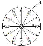
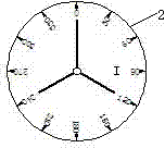
[0016] Depend on Figure 1-3 It can be seen from the illustrated embodiment that it includes a circular voltage phasor diagram board 1 with a 0°-360° phasor scale mark and a circular current phasor diagram board 2 with a 0°-360° phasor scale mark, The centers of the voltage phasor diagram 1 and the current phasor diagram 2 are connected by the rotating shaft 3; the voltage phasor diagram 1 and the current phasor diagram 2 have the same diameter, and the current phasor diagram 2 or the voltage phasor diagram located above Plate 1 is a transparent material.

[0017] The current phasor diagram 2 is located above the voltage phasor diagram 1, the current phasor diagram 2 is made of plastic, and the voltage phasor diagram 1 is made of copper.

[0018] The 0°-360° phasor scale of current phasor diagram board 2 is marked in red; the 0°-360° phasor scale of voltage phasor diagram board 1 is marked in black.

Embodiment 2

[0020] Including circular voltage phasor diagram 1 with 0°-360° phasor scale marking and circular current phasor diagram 2 with 0°-360° phasor scale marking, voltage phasor diagram 1 and The center of circle of the current phasor diagram 2 is connected by the rotating shaft 3; the diameter of the current phasor diagram 2 or the voltage phasor diagram 1 located above is smaller than the voltage phasor diagram 1 or the current phasor diagram 2 below, so that the following The 0°-360° phasor scale mark on the outer circle of the phasor diagram is not blocked by the upper phasor diagram.

[0021] The current phasor diagram 2 is located above the voltage phasor diagram 1, the current phasor diagram 2 is made of plastic, and the voltage phasor diagram 1 is made of copper.

[0022] The 0°-360° phasor scale of current phasor diagram board 2 is marked in red; the 0°-360° phasor scale of voltage phasor diagram board 1 is marked in black.

[0023] Instructions:

[0024] During the teac...


PUM


Abstract

The invention discloses a voltage and current rotation phasor drawing board, and relates to the technical field of teaching appliances. The voltage and current rotation phasor drawing board comprises a circular voltage phasor drawing board body with phasor scale markings from 0 degree to 360 degrees, and a circuit current phasor drawing board body with phasor scale markings from 0 degree to 360 degrees. The circle center of the voltage phasor drawing board body and the circle center of the current phasor drawing board body are connected through a rotating shaft. For the current phasor drawing board body and the voltage phasor drawing board body, the phasor drawing board body at the upper portion is smaller than the phasor drawing board body at the lower portion in diameter, so that the phasor scale markings, ranging from 0 degree to 360 degrees, of the outer ring of the phasor drawing board body at the lower portion are not blocked by the phasor drawing board body at the upper portion; or, the voltage phasor drawing board body and the current phasor drawing board body are the same in diameter, and the phasor drawing board body at the upper portion is transparent. The voltage and current rotation phasor drawing board has the advantages of being simple in structure, convenient to manufacture and the like, and is a good teaching auxiliary tool.

Description

technical field [0001] The invention relates to the technical field of teaching aids. Background technique [0002] At present, in the process of training and learning three-phase alternating current in electric power professional colleges and power supply enterprises, they just blindly draw phasor diagrams, and whenever the phase angle changes, they have to redraw the diagram. This form is an arduous process for beginners in professional colleges and employees with low levels of knowledge. This method cannot see the real thing, is very abstract, and is not easy to understand and master. On-site drawing is a waste of time, and the graphics are not accurate. affect the learning effect. Contents of the invention [0003] The technical problem to be solved by the present invention is to provide a voltage and current rotating phasor diagram, which has the characteristics of simple structure and convenient manufacture. The current and voltage phasors can be visually presente...

Claims


Application Information

Patent Timeline
Patent Type & Authority Applications(China)
IPC IPC(8): G09B23/18
Inventor 李会新
Owner STATE GRID CORP OF CHINA
Learn More