
Air-cooling reheating unit system arranged in small back-pressure type steam turbine and used for driving feed pump

A technology of steam-driven feed water pump and air cooling system, which is applied to machines/engines, steam engine devices, mechanical equipment, etc., can solve the problems of low thermal cycle efficiency, reduced thermal cycle efficiency, and reduced use efficiency of small steam turbines.

Active Publication Date: 2014-01-08
CHINA POWER ENG CONSULTING GRP CORP EAST CHINA ELECTRIC POWER DESIGN INST +1
View PDF7 Cites 16 Cited by
  • Summary
  • Abstract
  • Description
  • Claims
  • Application Information

AI Technical Summary

Problems solved by technology

[0009] As the exhaust steam through the reheater enters the medium pressure cylinder, the steam drawn out is reheated, the temperature increases, and the degree of superheat increases accordingly, so that the energy that could have been used to do work is used to heat condensed water and feed water, thus reducing Thermal Cycle Efficiency
And the exhaust steam after the small steam turbine does work is directly discharged to the air cooling system, which reduces the efficiency of the small steam turbine
[0010] Therefore, in order to solve the problem of low thermal cycle efficiency in existing air-cooled thermal power plants, it is necessary to design a new type of air-cooled reheat unit system with back-pressure small steam turbine driving feed water pump to improve energy utilization

Method used


Image

  • Air-cooling reheating unit system arranged in small back-pressure type steam turbine and used for driving feed pump
  • Air-cooling reheating unit system arranged in small back-pressure type steam turbine and used for driving feed pump
  • Air-cooling reheating unit system arranged in small back-pressure type steam turbine and used for driving feed pump

Examples


Embodiment

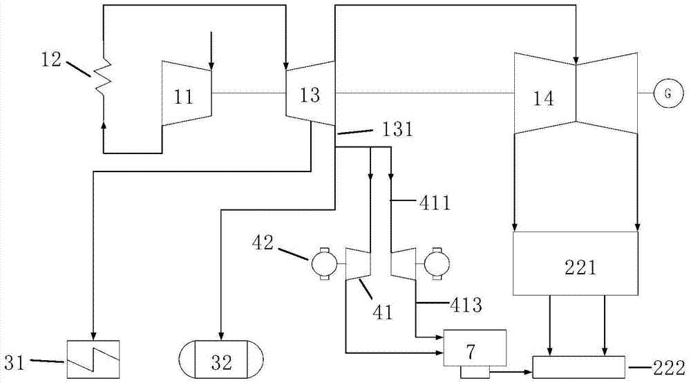
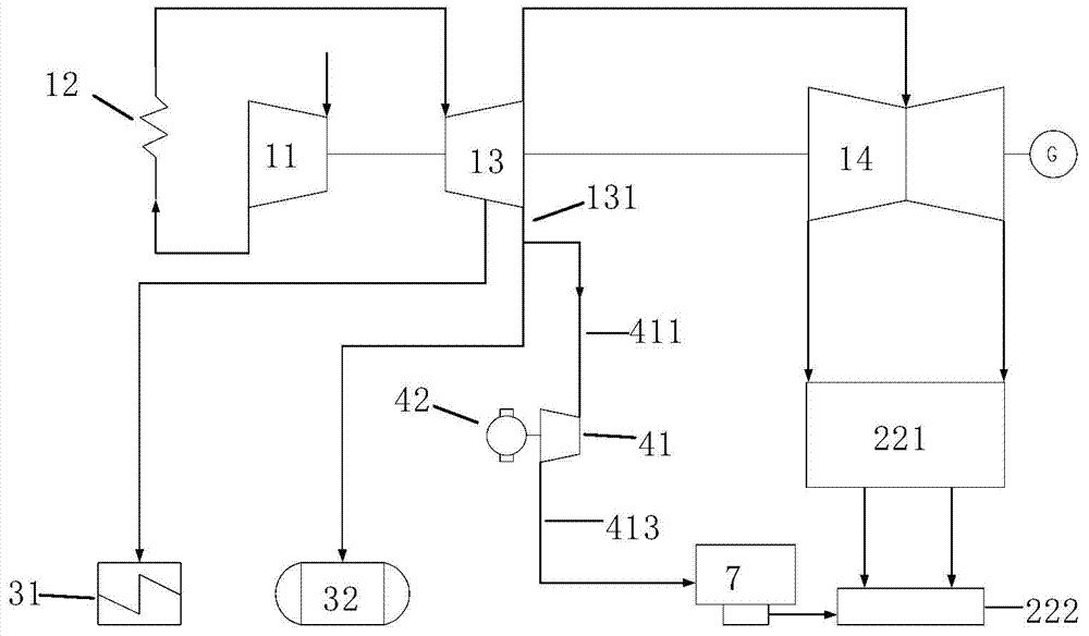
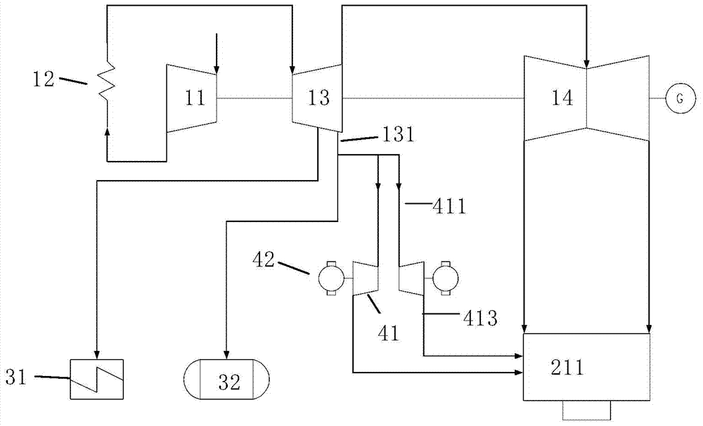
[0042] Figure 9-16 They are the system flow diagrams of 8 embodiments of the air-cooled reheating unit system driven by the back pressure small steam turbine of the present invention.

[0043] The air-cooled reheat unit system of the back-pressure small turbine-driven feedwater pump includes: reheat system, air-cooled system, back-pressure steam-driven feedwater pump system, heat recovery system, exhaust steam flow balance piping system and start-up exhaust steam piping system, among which , the reheat system can be a primary reheat system (including steam turbine high-pressure cylinder 11, reheater 12, steam turbine medium-pressure cylinder 13 and steam turbine low-pressure cylinder 14), or a secondary reheat system (including steam turbine ultra-high pressure cylinder 15, Primary reheater 121, steam turbine high pressure cylinder 11, secondary reheater 122, steam turbine medium pressure cylinder 13 and steam turbine low pressure cylinder 14).

[0044] The air cooling system ...


PUM


Abstract

The invention discloses an air-cooling reheating unit system arranged in a small back-pressure type steam turbine and used for driving a feed pump. Specifically, the air-cooling reheating unit system comprises a reheating system, an air cooling system, a back-pressure type pneumatic feed pump system and a heat regenerative system, wherein a steam inlet pipeline of the small back-pressure type steam turbine is connected with an exhaust steam pipeline of a steam turbine high pressure cylinder or a steam turbine ultrahigh pressure cylinder in the reheating system. An exhaust steam pipeline of the small back-pressure type steam turbine is connected with the heat regenerative system. According to the air-cooling reheating unit system arranged in the small back-pressure type steam turbine and used for driving the feed pump, steam before reheating is supplied for the small back-pressure type steam turbine to drive the feed pump and then the small back-pressure type steam turbine with the low superheat degree is utilized to pump the steam and exhaust the steam. A heater and / or a deaerator is used for heating condensation water and feedwater, the thermodynamic cycle efficiency of the system is improved and the heat exchange area of a reheater is reduced. Moreover, for a direct air cooling unit, a small steam turbine condenser and a small steam turbine indirect air cooling tower do not need to be arranged; for an indirect air cooling unit, the heat exchange area of an indirect air cooling tower of a main engine is saved.

Description

technical field [0001] The invention relates to the energy-saving technical field of power generation systems, in particular to an air-cooled reheating unit system with a back-pressure small turbine driving a feed water pump. Background technique [0002] Existing air-cooled thermal power plants using primary reheat or secondary reheat (hereinafter collectively referred to as reheat) technologies usually include a reheat system, a heat recovery system, an air cooling system, and a back-pressure steam-driven feedwater pump system, among which [0003] The reheat system is mainly to lead out the steam that has done part of the work in the main steam turbine for reheating, and then lead it back to the steam turbine to continue to work, thereby improving the efficiency of the thermal system. [0004] The heat recovery system is mainly to heat the condensed water and feed water with the heat extracted from the main steam turbine through the heater, thereby recovering all the heat...

Claims


Application Information

Patent Timeline
IPC IPC(8): F01K7/38F01D15/08
Inventor 张杰申松林林磊叶勇健陈仁杰施刚夜姚君董伦雄阳虹陈学文余炎范世望刘晓澜
Owner CHINA POWER ENG CONSULTING GRP CORP EAST CHINA ELECTRIC POWER DESIGN INST
Learn More