Rotate speed differential device

A speed difference and speed sensor technology, applied in the field of speed differential devices, can solve problems such as production cannot be carried out normally, damage, squeezing roller collision, etc., and achieve the effect of avoiding mutual jamming and damage

Active Publication Date: 2014-01-08
江阴迈森机械有限公司
View PDF5 Cites 0 Cited by
  • Summary
  • Abstract
  • Description
  • Claims
  • Application Information

AI Technical Summary

Problems solved by technology

[0002] At present, in the rubber plasticizing machine, each pair of extrusion rollers rotates at the same speed, which makes each pair of extrusion rollers often get stuck with each other, so that the production cannot be carried out normally and the extrusion rollers are damaged due to collision. damaged

Method used


Image

  • Rotate speed differential device

Examples


Embodiment Construction

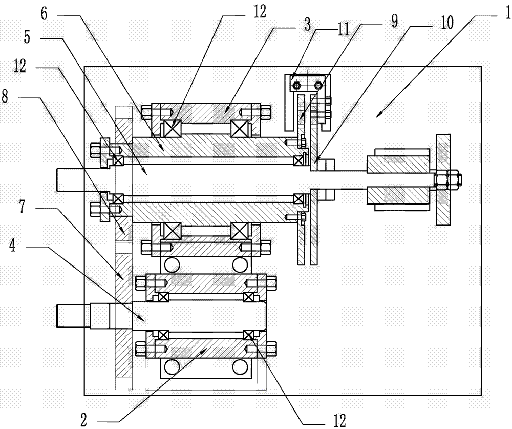
[0007] Such as figure 1 As shown, a speed differential device is characterized in that it includes a base 1, a bearing seat I2, a bearing seat II3, a rotating shaft I4, a rotating shaft II5, a sleeve shaft 6, a transmission gear I7, a transmission gear II8, a rotary piece I9, and a rotary piece II10, speed sensor 11 and bearing 12; bearing housing I2 and bearing housing II3 are installed side by side on base 1, rotating shaft I4 is installed in bearing housing I2 through bearing 12, sleeve shaft 6 is installed in bearing housing II3 through bearing 12, rotating shaft II5 Installed in the sleeve shaft 6 through the bearing 12, the two ends of the shaft II5 protrude from the sleeve shaft 6, and a transmission gear I7 is installed at the front end of the shaft I4; a transmission gear II8 connected with the teeth of the transmission gear I7 is installed at the front end of the sleeve shaft 6, A rotary piece I9 is ​​connected to the rear end of the sleeve shaft 6; a rotary piece I...


PUM


Abstract

The invention relates to a rotate speed differential device. The rotate speed differential device is characterized by comprising a base, a bearing support I, a bearing support II, a rotating shaft I, a rotating shaft II, a sleeve shaft, a transmission gear I, a transmission gear II, a rotor I, a rotor II, a rotation speed sensor and a bearing. The rotate speed differential device has the advantage that two extrusion rollers can be prevented from being blocked and damaged mutually.

Description

technical field [0001] The invention relates to a differential device, in particular to a rotational speed differential device. technical background [0002] At present, in the rubber plasticizing machine, each pair of extrusion rollers rotates at the same speed, which makes each pair of extrusion rollers often get stuck with each other, so that the production cannot be carried out normally and the extrusion rollers are damaged due to collision. damaged. Contents of the invention [0003] In view of the above disadvantages, the object of the present invention is to provide a rotational speed differential device which can avoid mutual jamming and damage of the two extrusion rollers. [0004] The technical content of the present invention is a speed differential device, which is characterized in that it includes a base, a bearing seat I, a bearing seat II, a rotating shaft I, a rotating shaft II, a sleeve shaft, a transmission gear I, a transmission gear II, a rotating piec...

Claims


Application Information

Patent Timeline
IPC IPC(8): B29B7/56B29B7/72
Inventor 夏洪雷徐锦张杨
Owner 江阴迈森机械有限公司
Why Eureka
Try Eureka