
Robotic Arm Control

A control device, robotic arm technology, applied in the direction of manipulator, program control, general control system, etc., can solve problems such as changing programs

Inactive Publication Date: 2016-05-04
MITSUBISHI ELECTRIC CORP
View PDF8 Cites 0 Cited by
  • Summary
  • Abstract
  • Description
  • Claims
  • Application Information

AI Technical Summary

Problems solved by technology

In addition, when the surrounding environment has a complex shape, or the surrounding environment is changed or added midway, it will cause trouble to change the program

Method used


Image

  • Robotic Arm Control
  • Robotic Arm Control
  • Robotic Arm Control

Examples


Embodiment approach

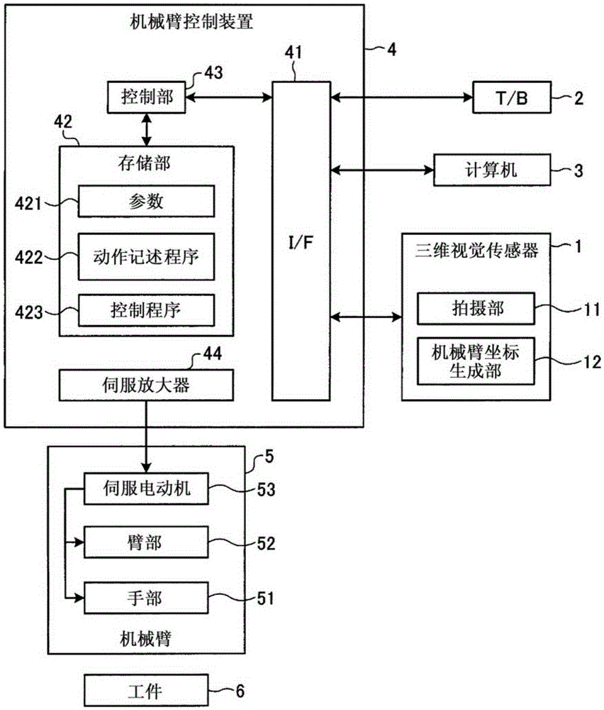
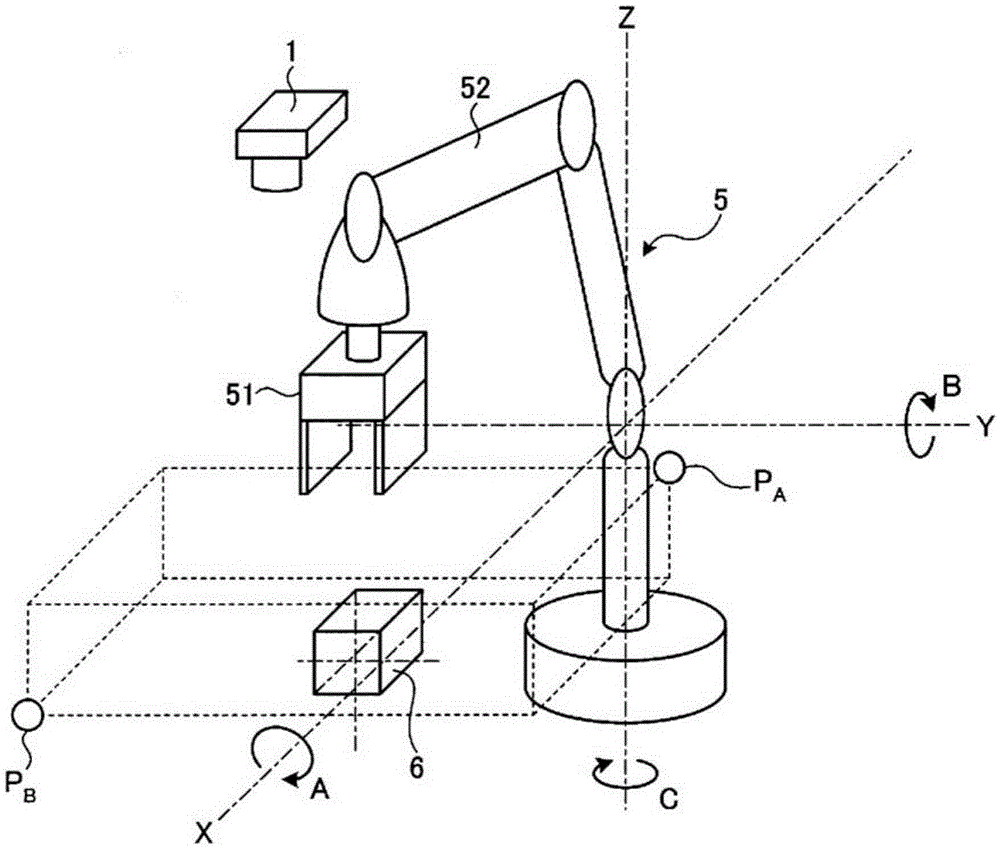
[0028] figure 1 It is a figure which shows the structure of the robot arm control system in which the embodiment of the robot arm control apparatus which concerns on this invention is used. The manipulator control system has a three-dimensional vision sensor 1, a teaching box (T / B) 2, a computer 3, a manipulator control device 4 and a manipulator 5, and the manipulator 5 is used to grasp and move the workpiece 6.

[0029] The three-dimensional vision sensor 1 serving as a workpiece detection unit includes an imaging unit 11 that generates image data by imaging, and a robot arm coordinate generation unit 12 that processes the image data generated by the imaging unit 11 to generate coordinate data of the robot arm.

[0030] The robotic arm control device 4 has: an interface (I / F) 41, which is used to transmit / receive data with the three-dimensional vision sensor 1, T / B 2, and computer 3; a storage unit 42, which stores various parameters 421 and action descriptions; The program...


PUM


Abstract

It has: a storage unit (42) that uses as parameters a non-interference area where the hand (51) does not interfere with the surrounding environment and a workpiece area where the hand (51) can pass when grasping the workpiece (6) (421) store; and the control unit (43), which executes the action description program (422) including the command string in the order of the take-out action, so that the mechanical arm (5) drives the arm (52) and the hand (51) Move, read the parameters (421) of the workpiece area from the storage unit (42), and calculate the position and direction of the workpiece area based on the position and posture of the workpiece (6) acquired from the three-dimensional vision sensor (1), The parameter of the non-interference area is read from the storage unit (42), and the overlapping portion between the surrounding environment area and the workpiece area whose position and direction have been calculated is calculated, and when there is an overlapping portion between the surrounding environment area and the workpiece area, When the hand (51) enters the workpiece area, a predetermined motion is performed as an interference motion.

Description

technical field [0001] The invention relates to a mechanical arm control device. Background technique [0002] Currently, the robotic arm control device connected to the robotic arm and the three-dimensional vision sensor takes out the robotic arm for the target workpiece identified by the three-dimensional visual sensor, and moves it from the overhead position to the position where the target workpiece is detected. Take out the object workpiece with the hand at the tip of the arm. At this time, the robot arm control device drives the arm so as to move the hand from an overhead position to a position where the target workpiece is recognized and detected by the three-dimensional vision sensor, thereby taking out the target workpiece. [0003] When moving the hand linearly from the overhead position to the position where the target workpiece is recognized and detected by the 3D vision sensor, it may interfere with the surrounding environment (peripheral tools, a box containin...

Claims


Application Information

Patent Timeline
Patent Type & Authority Patents(China)
IPC IPC(8): B25J13/00B25J19/06
CPCB25J9/1666G05B2219/40476G05B2219/40478G05B2219/40479G05B2219/40492G05B2219/49137B25J9/1612
Inventor 松井则夫
Owner MITSUBISHI ELECTRIC CORP
Learn More