Box girder vertical bending moment test mechanism

A vertical bending moment, box beam technology, applied in the testing of mechanical components, testing of machine/structural components, measuring devices, etc., can solve the problem of inability to accurately collect data, and achieve easy acquisition, novel structure, and structural span. added effect

Active Publication Date: 2016-05-04
HARBIN ENG UNIV
View PDF4 Cites 0 Cited by
  • Summary
  • Abstract
  • Description
  • Claims
  • Application Information

AI Technical Summary

Problems solved by technology

In the case of a small-scale test member, when the bending moment test is performed on it, it will be damaged due to excessive pressure without bending, and the required data cannot be accurately collected

Method used


Image

  • Box girder vertical bending moment test mechanism
  • Box girder vertical bending moment test mechanism
  • Box girder vertical bending moment test mechanism

Examples


Embodiment Construction

[0015] The present invention is described in more detail below in conjunction with accompanying drawing example:

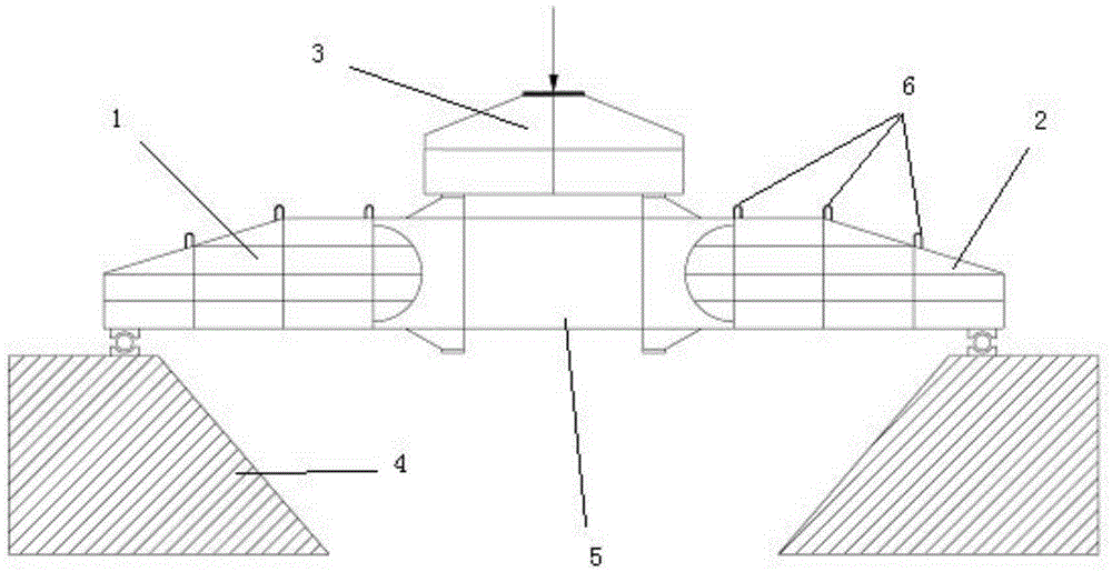
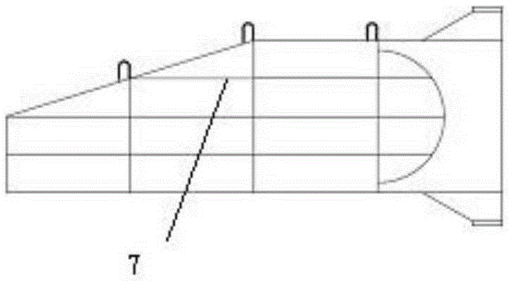
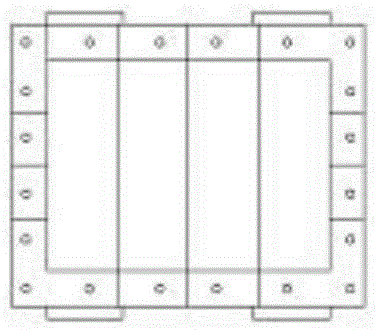
[0016] combine Figure 1~4 ,exist figure 1 In , the schematic diagram shows the box beam vertical bending moment test mechanism. The left connecting bridge 1 and the right connecting bridge 2 are connected together with the model test section 5 by bolts, and the whole structure is placed on the support base 4 . The loading mechanism 3 is placed on the model test section, and the upper end faces of the left connecting bridge 1 and the right connecting bridge 2 are installed with lifting lugs 6 . In the three views of the connecting bridge structure in Fig. 2, the connecting bridge 1 on the left and the connecting bridge 2 on the right are provided with reinforcing ribs 7. In FIG. 3 , the loading mechanism 3 is placed on the model test section 5 . For the details of simply supported end of the base, see Figure 4 , weld the shaft seat 12 at the tail of the left...


PUM


Abstract

The invention provides a box beam vertical moment test mechanism which comprises a loading mechanism, connecting bridges and supporting bases. The connecting bridges comprise a left connecting bridge and a right connecting bridge, the supporting bases comprise a left supporting base and a right supporting base, bolt holes are formed in the left connecting bridge and the right connecting bridge, a model test section is arranged between the left connecting bridge and the right connecting bridge through bolts, shaft supports are arranged on the lower end face of the left connecting bridge and the lower end face of the right connecting bridge, shaft supports are arranged on the upper end face of the left supporting base and the upper end face of the right supporting base, the shaft support of the left connecting bridge is arranged on the shaft support of the left supporting base through a first rolling shaft, the shaft support of the right connecting bridge is arranged on the shaft support of the right supporting base through a second rolling shaft, and the loading mechanism is arranged on the model test section. The box beam vertical moment test mechanism is novel in structure, the span of the whole structure is increased through the components, and the deformation of a local test piece is monitored through overall deformation. Under the condition of even loading, the data needed in the test can be collected more easily.

Description

technical field [0001] The invention relates to a test mechanism, specifically a bending moment test mechanism. Background technique [0002] A ship is a complex water engineering structure. It is responsible for a series of tasks such as transportation and production. Therefore, the ship should have good performance and have a certain strength. The hull structure should have the ability not to be damaged or excessively deformed during normal use and a certain service life, so as to ensure that the ship can work normally. Designers should ensure that the ship has sufficient strength in sailing state. [0003] When a ship travels on the sea, due to the different weights of the local sections of the hull, the force on the water surface is uneven. The conventional method is to calculate the overall longitudinal strength of the hull. Put the hull on the waves, find the total longitudinal bending moment and the corresponding total longitudinal bending stress, and compare it ...

Claims


Application Information

Patent Timeline
Patent Type & Authority Patents(China)
IPC IPC(8): G01M13/00
Inventor 李陈峰任慧龙邹佳星冯国庆李辉刘宁赵晓东
Owner HARBIN ENG UNIV
Why Eureka
Try Eureka