time-of-flight mass analyzer

A mass analysis device and time-of-flight technology, applied in the field of ion incident optical systems, can solve the problems of reliability, troublesome operation, labor-intensive and other problems, and achieve the effect of easy assembly, easy manufacture, and reduced angular spread

Inactive Publication Date: 2016-02-17
SHIMADZU SEISAKUSHO CO LTD
View PDF6 Cites 0 Cited by
  • Summary
  • Abstract
  • Description
  • Claims
  • Application Information

AI Technical Summary

Problems solved by technology

[0010] In addition, in the above-mentioned conventional structure, the mass resolution is determined by the gap between the two slit plates and the width of the slit opening. Therefore, for example, it is desirable to perform high-sensitivity measurement even if the mass resolution is slightly lowered. Requirements, mechanical operations such as replacing the slit plate of the beam limiting mechanism with a slit plate with a different slit opening width or adjusting the gap between the slit plates
Such an operation is cumbersome and labor-intensive
In addition, there is also a problem in the reliability of the mechanism that can perform such mechanical adjustment and replacement.

Method used


Image

  • time-of-flight mass analyzer
  • time-of-flight mass analyzer
  • time-of-flight mass analyzer

Examples


Embodiment Construction

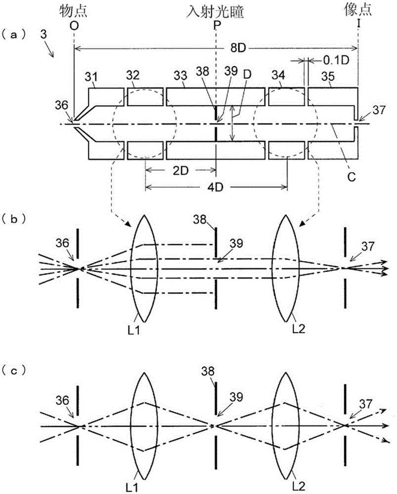
[0054] The orthogonal acceleration method TOFMS of an embodiment of the present invention will be described with reference to the drawings. figure 2 It is the overall structure diagram of the orthogonal acceleration mode TOFMS of this embodiment, figure 1 It is a schematic structure diagram (a) and optical equivalent structure diagrams (b) and (c) of the ion incident optical system in the orthogonal acceleration method TOFMS.

[0055] The orthogonal acceleration method TOFMS of this embodiment includes: an ion source 1, which ionizes a target sample; a TOF analyzer 5, which includes a reflector 51; and an orthogonal acceleration section 4, which accelerates ions and sends them into the TOF Analyzer 5; Electrostatic lens 3, which sends ions emitted from the ion source 1 into the orthogonal acceleration part 4; Detector 6, which detects ions flying in the flight space of the TOF analyzer 5; Data processing part 16 , Which processes the data obtained by the detector 6 to produce, f...


PUM


Abstract

An electrostatic lens (3), including five cylindrical electrodes (31-35) arrayed along an ion-optical axis (C) and an aperture plate (38) located on a common focal plane of two virtual convex lenses (L1 and L2) formed under an afocal condition, is used as an ion-injecting optical system for sending ions into an orthogonal acceleration unit. The diameter of a restriction aperture (39) formed in the aperture plate (38) determines the angular spread of an exit ion beam. When voltages for making the electrostatic lens (3) function as an afocal system are set, a measurement with high mass-resolving power can be performed at a slight sacrifice of the sensitivity. When voltages for making the lens function as a non-afocal system having the highest ion-passage efficiency are set, a measurement with high sensitivity can be performed at a slight sacrifice of the resolving power. Thus, the operation of an orthogonal acceleration TOFMS can easily be switched between a mode with priority put on the mass-resolving power and a mode with priority put on the measurement sensitivity.

Description

Technical field [0001] The present invention relates to a time-of-flight mass analysis device, and more specifically, to a time-of-flight mass analysis device in an orthogonal acceleration mode (also sometimes referred to as a vertical acceleration mode) that enters ions into an orthogonal acceleration part Ion incident optical system. Background technique [0002] In a time-of-flight mass spectrometer (hereinafter referred to as "TOFMS"), fixed kinetic energy is given to ions derived from sample components to make them fly in a fixed distance space, and the time required for the flight is measured, according to This flight time finds the mass-to-charge ratio of the ion. Therefore, one of the major reasons for the reduction of mass resolution in TOFMS is the deviation of the initial energy of ions. In contrast, in the reflector-type TOFMS, the reflector has the function of correcting the difference in motion energy. A detailed description is omitted, but in a known two-stage r...

Claims


Application Information

Patent Timeline
Patent Type & Authority Patents(China)
IPC IPC(8): H01J49/40G01N27/62H01J49/06
CPCH01J49/067H01J49/401
Inventor 古桥治谷口纯一
Owner SHIMADZU SEISAKUSHO CO LTD
Why Eureka
Try Eureka