
Conveying system, and use of a chamber extending inwardly with respect to a plastic module in a conveying system

A technology of conveying system and conveying direction, applied in the direction of conveyor, transportation and packaging, packaging, etc., can solve the problems of long logistics, disadvantage, long delivery time, etc.

Inactive Publication Date: 2013-12-18
REXNORD FLATTOP EURO BV
View PDF5 Cites 0 Cited by
  • Summary
  • Abstract
  • Description
  • Claims
  • Application Information

AI Technical Summary

Problems solved by technology

For the supplier, this would bring e.g. a large inventory containing many different modules and pads, which is disadvantageous
This would further lead to longer lead times, for example, due to suppliers not having suitable modules and / or pads in stock and / or due to logistical complications resulting from this
This is not advisable as it would cause, for example, a production line of which the conveying system is a part to be left unused for a long period of time.
There is also a disadvantage: the manufacturer of plastic modules for the manufacture of different modules with cavities of different sizes needs to invest in different means of production, such as different injection molds for different modules with cavities of different sizes
This would likewise lead to a large inventory for the manufacturer and / or distributor and, for example, the delivery time from the manufacturer to one of his buyers would become longer

Method used


Image

  • Conveying system, and use of a chamber extending inwardly with respect to a plastic module in a conveying system
  • Conveying system, and use of a chamber extending inwardly with respect to a plastic module in a conveying system
  • Conveying system, and use of a chamber extending inwardly with respect to a plastic module in a conveying system

Examples


Embodiment Construction

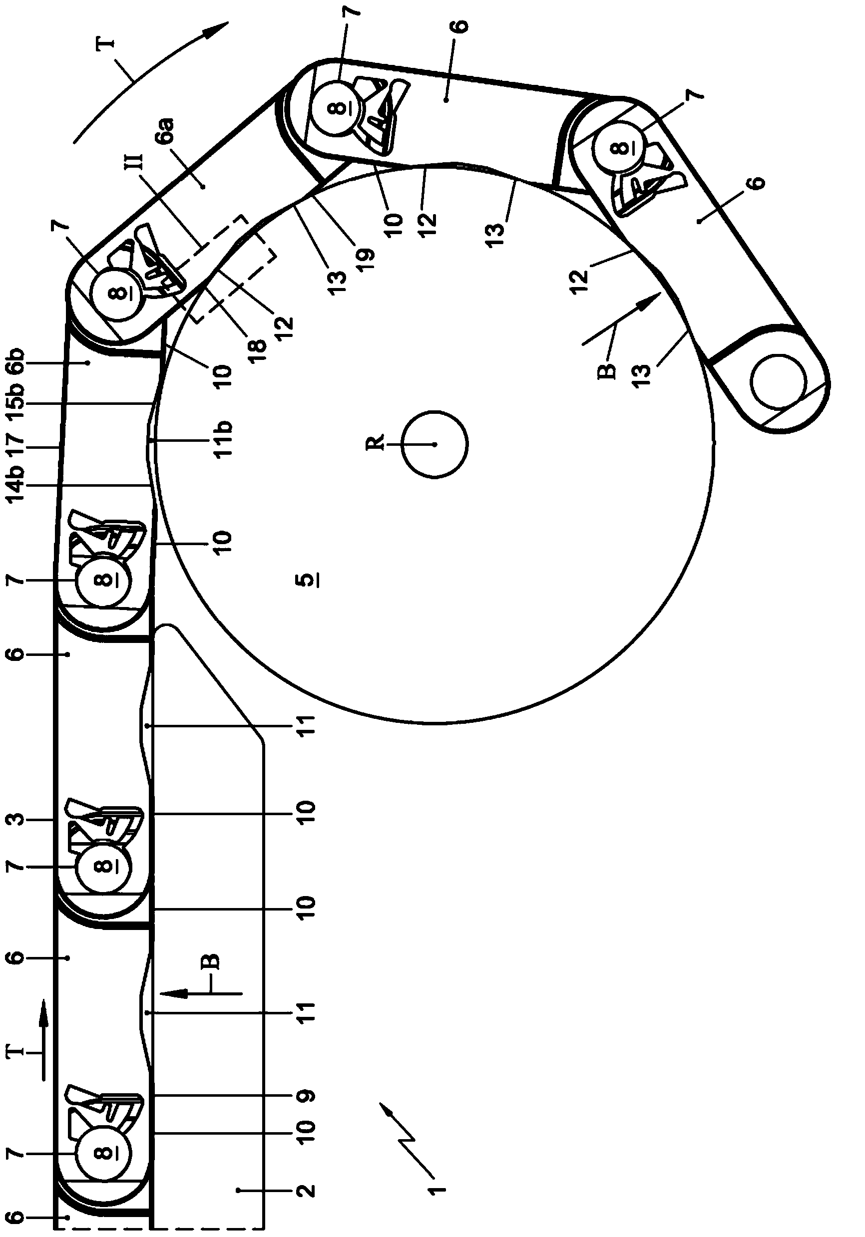
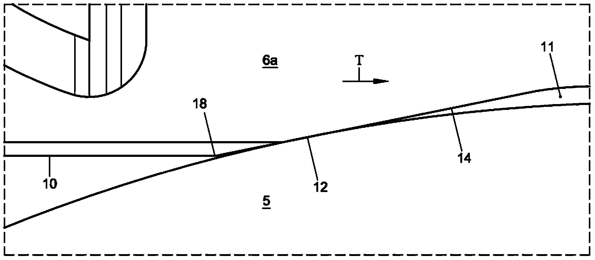
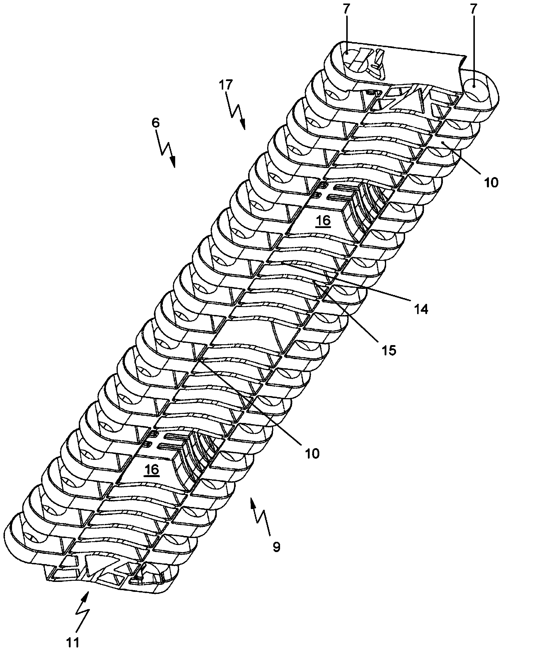
[0030] figure 1 A schematic cross-sectional view of part of a delivery system 1 according to the invention is shown. Said conveying system 1 comprises a conveying track 2, a continuous conveyor liner 3 intended to rotate around said conveying track 2 and suitable for conveying products in a conveying direction T, a drive (not shown) driving said conveyor liner 3 ), and a non-driven return guide 5 arranged on the conveyor track 2 for guiding the conveyor liner 3 during rotation, said non-driven return guide 5 being substantially transverse to the conveying direction T extend. The conveyor liner 3 comprises a plurality of plastic modules 6 which are continuous in the conveying direction T and extend transversely with respect to the conveying direction T, wherein each plastic module, viewed in the conveying direction T, has hinge loops on its front and rear sides 7. The hinge rings 7 of the successive modules 6 in the conveying direction T are connected and cooperate by means ...


PUM


Abstract

The invention relates to a conveying system (1). The conveying system (1) comprises a conveying track (2), an endless conveyor mat (3) for conveying products in a conveying direction (T), a drive for driving the conveyor mat (3), and a return guide (5) provided at the conveying track (2) for guiding the conveyor mat (3) upon circulation. The return guide (5) extends substantially transversely to the conveying direction (T). The conveyor mat (3) comprises a number of plastic modules (6), which are provided at their bottom side with a track guide surface (10), while at least a part of the plastic modules (6) at the location of the respective track guide surface (10) comprise at least one chamber (11) extending inwardly with respect to the module (6) for being in a contact with the return guide (5) during circulation of the module (6) around the return guide (5). The chamber (11) is formed such that the contact upon circulation consists of a first line contact (12) and a second line contact (13).

Description

technical field [0001] The invention relates to a conveying system comprising a conveying track, a continuous conveyor liner intended to rotate around said conveying track and suitable for conveying products in a conveying direction, a drive for driving said conveyor liner, and a a conveyor track, a non-driven return guide for guiding the conveyor liner as it rotates, the return guide extending substantially transversely with respect to the direction of conveyance, wherein the conveyor liner comprises a plurality of Plastic modules that are continuous on the top and extend transversely relative to the conveying direction, wherein, viewed from the conveying direction, each plastic module is provided with hinge rings on the front and rear sides, and the hinge rings of the modules that are continuous in the conveying direction are Hinge pins extending transversely to the conveying direction are coupled and cooperate, wherein when the plastic modules are guided on rails, their sid...

Claims


Application Information

Patent Timeline
Patent Type & Authority Applications(China)
IPC IPC(8): B65G17/08B65G17/40
CPCB65G17/40B65G17/08B65G2207/12
Inventor 莱昂纳德斯·阿德里安乌斯·卡塔里纳斯·科内利森罗纳德·西格蒙德
Owner REXNORD FLATTOP EURO BV
Learn More