Macro fill light module with flexible circuit board

A technology for flexible circuit boards and circuit board components, which is applied in optics, instruments, photography, etc., and can solve problems such as affecting output efficiency, internal circuit breakers, and yield reduction.

Inactive Publication Date: 2016-08-10
LUMOS TECH
View PDF5 Cites 0 Cited by
  • Summary
  • Abstract
  • Description
  • Claims
  • Application Information

AI Technical Summary

Problems solved by technology

[0003] With the expansion of the macro photography market, manufacturers have developed a variety of macro supplementary light modules, usually a group of supplementary light modules that use light-emitting diodes as artificial light sources in front of the lens, such as figure 1 As shown, the light-emitting diode 92 is welded on the hard circuit board 93, but the lead wire 921 that is fine and has a certain length not only must be installed manually by skilled assemblers, but also is easy to be pulled during the installation process, which increases the difficulty of assembly. , it may also cause poor signal and energy conduction due to slight pulling, and reduce the yield; moreover, each hard circuit board 93 must also be manually screwed to the sleeve 91 with the screws 94 one by one , affecting the output efficiency; what’s more, in order to adjust the fill light angle, the hard circuit board 93 must be rotated frequently, not only the possibility of the lead wire 921 being hooked, but also the lead wire 921 may be bent repeatedly, resulting in poor contact or Internal open circuit, reducing service life and increasing maintenance troubles
[0004] In recent years, in addition to the general and customary uses of macro photography, many special uses have been developed, such as banknote anti-counterfeiting, medical cosmetology, skin diagnosis and treatment, criminal identification, etc., especially in some fields involving fluorescence. Therefore, it is also necessary to Provide short-distance supplementary light modules such as ultraviolet light; on the other hand, a microscope is another image analysis device that will be equipped with a supplementary light module. Microscopic section images are faint

Method used


Image

  • Macro fill light module with flexible circuit board
  • Macro fill light module with flexible circuit board
  • Macro fill light module with flexible circuit board

Examples


Embodiment Construction

[0040] The aforementioned and other technical contents, features and effects of the present invention will be clearly presented in the following detailed description of preferred embodiments with accompanying drawings.

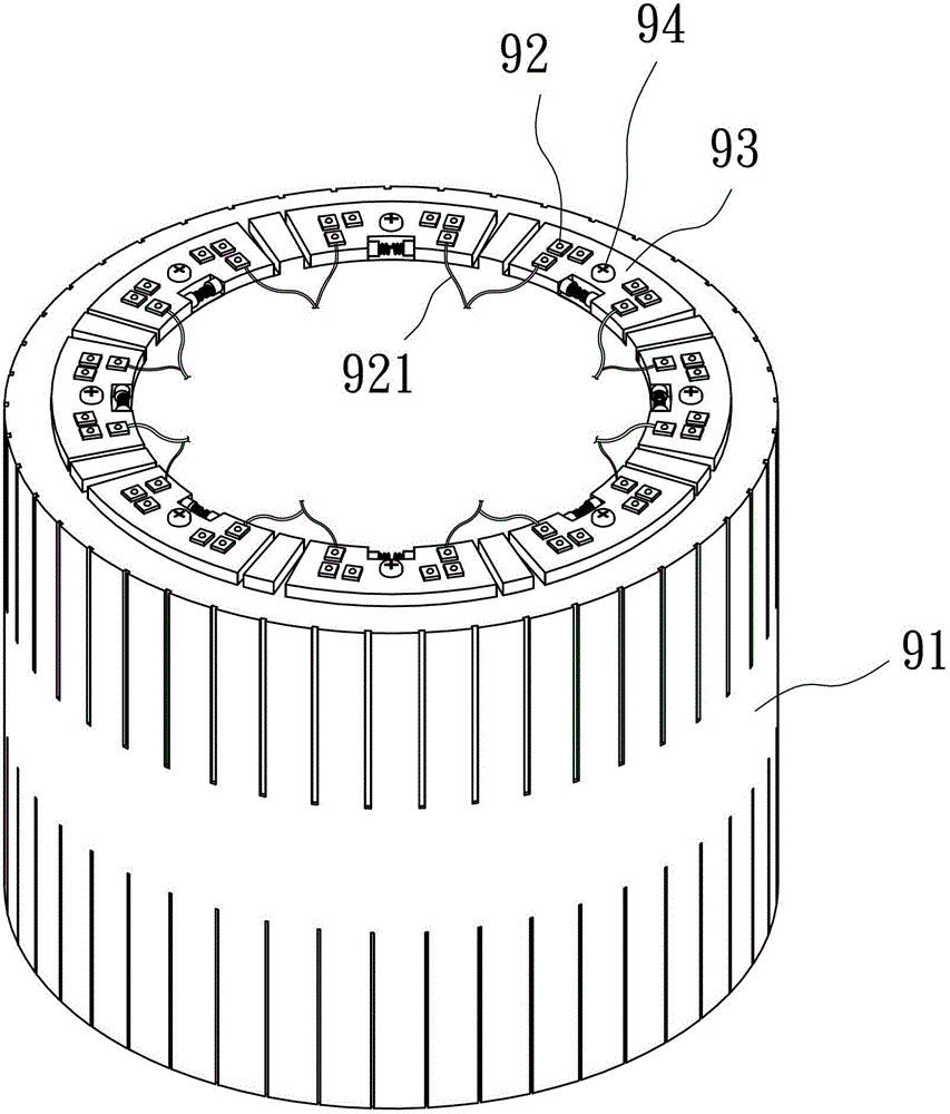
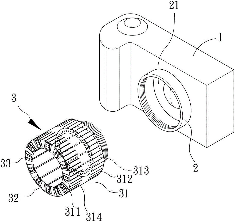
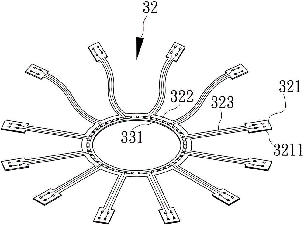
[0041] The first preferred embodiment of the present invention is Figure 2 to Figure 4 As shown, the optical image analysis device mainly includes a body 1, a lens 2 at the front end of the body 1, and a macro light supplement module 3 screwed on the lens 2. For the sake of illustration, the front of the lens 2 is defined here as The light entrance 21, all the image beams enter through the light entrance 21, therefore, the macro-distance supplementary light module 3 is screwed to the light entrance 21 correspondingly, and includes a sleeve 31, a circuit board assembly 32, a light emitting The component 33 and the angle adjustment component 34; in this embodiment, the optical image analysis device is illustrated as a single-eye camera, but it is not limited to...


PUM


Abstract

A macro-distance supplementary light module with a flexible circuit board is for use with an optical image analysis device, and the optical image analysis device has a light entrance, and the macro-distance supplementary light module is for correspondingly arranged on the light entrance place, and includes: a sleeve; at least one piece of circuit board assembly including at least one flexible circuit board and a plurality of composite board areas respectively with hard board liners, and assembled in the sleeve; a set of light emitting components, including multiple Two light-emitting elements respectively arranged on the composite plate area and having light-emitting surfaces; and a group of angle adjustment components, including a plurality of pivoting parts that respectively drive the composite plate area to pivot relative to the sleeve and adjust the light emitting angle of the light-emitting element.

Description

【Technical field】 [0001] The invention relates to a macro-distance supplementary light module, in particular to a macro-distance supplementary light module with a flexible circuit board. 【Background technique】 [0002] Professionally, macro photography refers to photography with a magnification of one time the size of the real object or greater. In simple terms, it is to compare the real object with its image size on the film or CCD, both of which have exactly the same size. However, the shooting distance is usually only 5 to 8 cm. At such a short distance, if you want to get enough depth of field (the clear range of the image in front and behind the focus point), the aperture must be reduced quite small (f / 16, f / 22 ), and compared with the longer exposure time of ordinary cameras, if the shooting skills are not skilled enough, it is easy to take dim and blurred pictures. In order to solve the above problems, an external fill light device is often used to connect to the fro...

Claims


Application Information

Patent Timeline
Patent Type & Authority Patents(China)
IPC IPC(8): G03B15/05G03B15/03
Inventor 杨之逸
Owner LUMOS TECH
Why Eureka
Try Eureka