
Lifting rod and illuminating lamp

A lifting rod and section rod technology, which is applied to lighting devices, lighting auxiliary devices, lighting and heating equipment, etc., can solve the problems of difficulty in controlling the relative rotation of the lifting section rod, and the irradiation direction of the lamp head is not fixed, and achieves a simple and reliable overall structure. Enhanced strength and easy installation

Inactive Publication Date: 2013-12-18
OCEANS KING LIGHTING SCI&TECH CO LTD +1
View PDF7 Cites 1 Cited by
  • Summary
  • Abstract
  • Description
  • Claims
  • Application Information

AI Technical Summary

Problems solved by technology

[0002] Generally, products with lifting rod structure, such as lighting fixtures, will rotate between the lifting rods when the lifting rod is used, resulting in the problem that the direction of the lamp head is not fixed when lifting, especially when there are more than two lifting rods , the relative rotation between the lifting joints is difficult to control

Method used


Image

  • Lifting rod and illuminating lamp
  • Lifting rod and illuminating lamp
  • Lifting rod and illuminating lamp

Examples


Embodiment Construction

[0022] The following will clearly and completely describe the technical solutions in the embodiments of the present invention with reference to the drawings in the embodiments of the present invention.

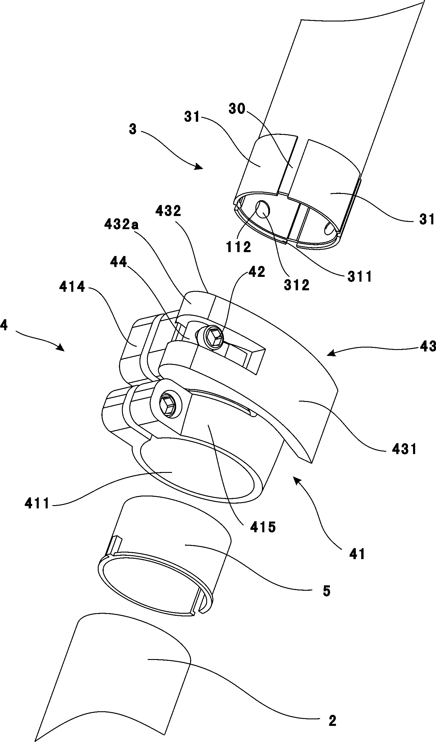
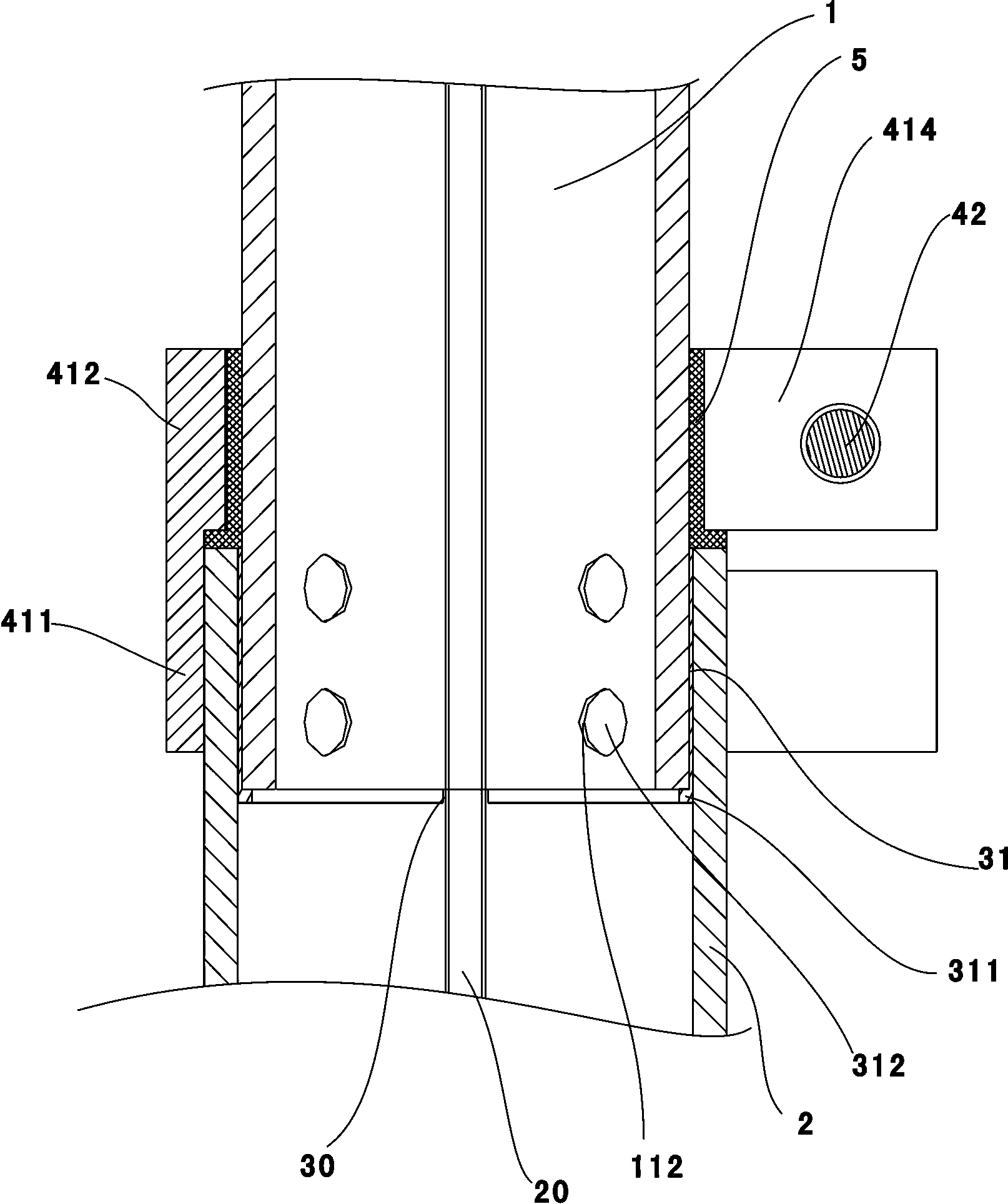
[0023] see figure 1 and figure 2 , a lighting fixture provided in an embodiment of the present invention includes a lifting rod 100 and a lighting lamp (not shown in the figure) connected to the lifting rod 100 . The lifting rod 100 includes at least two tubular lifting joints, a plastic bushing 3 and a locking mechanism 4 , which are sheathed in sequence from the inside to the outside, and the lighting lamp is fixed on the innermost lifting joint. The two adjacent lifting sub-rods in at least two lifting joints are respectively the inner joint 1 and the outer joint 2, such as Figure 2 to Figure 4 As shown, the plastic bushing 3 is fixed on the inner section bar 1 and is slidably arranged at one end of the outer section bar 2. The inner side wall of the outer section bar 2...


PUM


Abstract

The invention discloses a lifting rod. The lifting rod comprises at least two lifting section rods, plastic bushings and locking mechanisms, the lifting section rods are tubular and sleeved sequentially from inside to outside, every two adjacent lifting section rods are an inner section rod and an outer section rod respectively, each plastic bushing is fixedly arranged in the corresponding inner section rod and slidingly arranged at one inner end of the corresponding outer section rod, ribs are arranged on the inner side wall of each outer section rod, sliding grooves matched with the ribs are formed in each plastic bushing, and the ribs and the sliding grooves are all strip-shaped and arranged along the axial direction of the lifting rod. The locking mechanisms are used for locking the inner section rods and the outer section rods. Or, sliding grooves are formed in the inner side wall of each outer section rod, and ribs are arranged on each plastic bushing. Through matching of the sliding grooves and the ribs, relative circumferential rotation between the inner section rods and the outer section rods is avoided; by the aid of the plastic bushings, the inner section rods and the outer section rods of the lifting rod cannot generate friction to be worn, and service life of the lifting rod can be prolonged accordingly; the plastic bushings are located in the outer section rods constantly, and thereby attractiveness in overall appearance of the lifting rod is unaffected. Meanwhile, the invention further discloses an illuminating lamp.

Description

technical field [0001] The invention relates to a lifting rod and a lighting fixture. Background technique [0002] Generally, products with lifting rod structure, such as lighting fixtures, will rotate between the lifting rods when the lifting rod is used, resulting in the problem that the direction of the lamp head is not fixed when lifting, especially when there are more than two lifting rods , the relative rotation between the lifting joints is difficult to control. Therefore how to ensure that the lifting rods will not rotate mutually between the lifting rods during use is an urgent problem to be solved. Contents of the invention [0003] The object of the present invention is to provide a lifting rod and a lighting fixture with simple structure and no relative rotation between the lifting joints. [0004] In order to solve the above-mentioned technical problems, the present invention provides a lifting rod, which includes at least two tubular lifting rods that are ...

Claims


Application Information

Patent Timeline
Patent Type & Authority Applications(China)
IPC IPC(8): F21V21/22
Inventor 周明杰黄剑云
Owner OCEANS KING LIGHTING SCI&TECH CO LTD
Learn More