Hydraulic cylinder

A technology of hydraulic cylinders and cylinders, applied in the field of hydraulic cylinders, can solve the problems of reducing the power of the piston 3, increasing the complexity of piping outside the cylinder, increasing the risk of damage to seals, etc. simple effect

Active Publication Date: 2013-12-18
河北雷萨重型工程机械有限责任公司
View PDF6 Cites 5 Cited by
  • Summary
  • Abstract
  • Description
  • Claims
  • Application Information

AI Technical Summary

Problems solved by technology

figure 2 In the hydraulic cylinder, a one-way valve 10 is arranged on the cylinder barrel 1 of the hydraulic cylinder. When the piston 3 moves to the right and makes the first chamber A communicate with the second chamber B, the oil in the first chamber A flows into the Although the second chamber B can reduce the power of the piston 3, since it is necessary to set an opening in the cylinder 1 that communicates with the check valve 10, the risk of damage to the seal is increased, and the complexity of piping outside the cylinder is also increased. sex

Method used


Image

  • Hydraulic cylinder
  • Hydraulic cylinder
  • Hydraulic cylinder

Examples


Embodiment Construction

[0032] Specific embodiments of the present invention will be described in detail below in conjunction with the accompanying drawings. It should be understood that the specific embodiments described here are only used to illustrate and explain the present invention, and are not intended to limit the present invention.

[0033] In the present invention, in the case of no contrary description, the terms "first" and "second" used are only used to illustrate the present invention, and there is no distinction between primary and secondary; the orientation words "left, right" are according to defined in the orientation shown in the drawing.

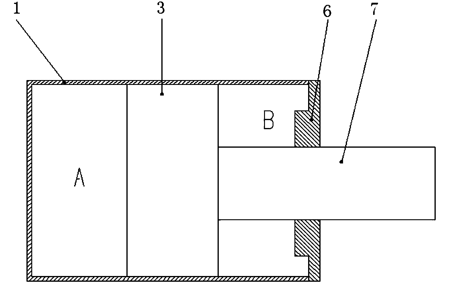
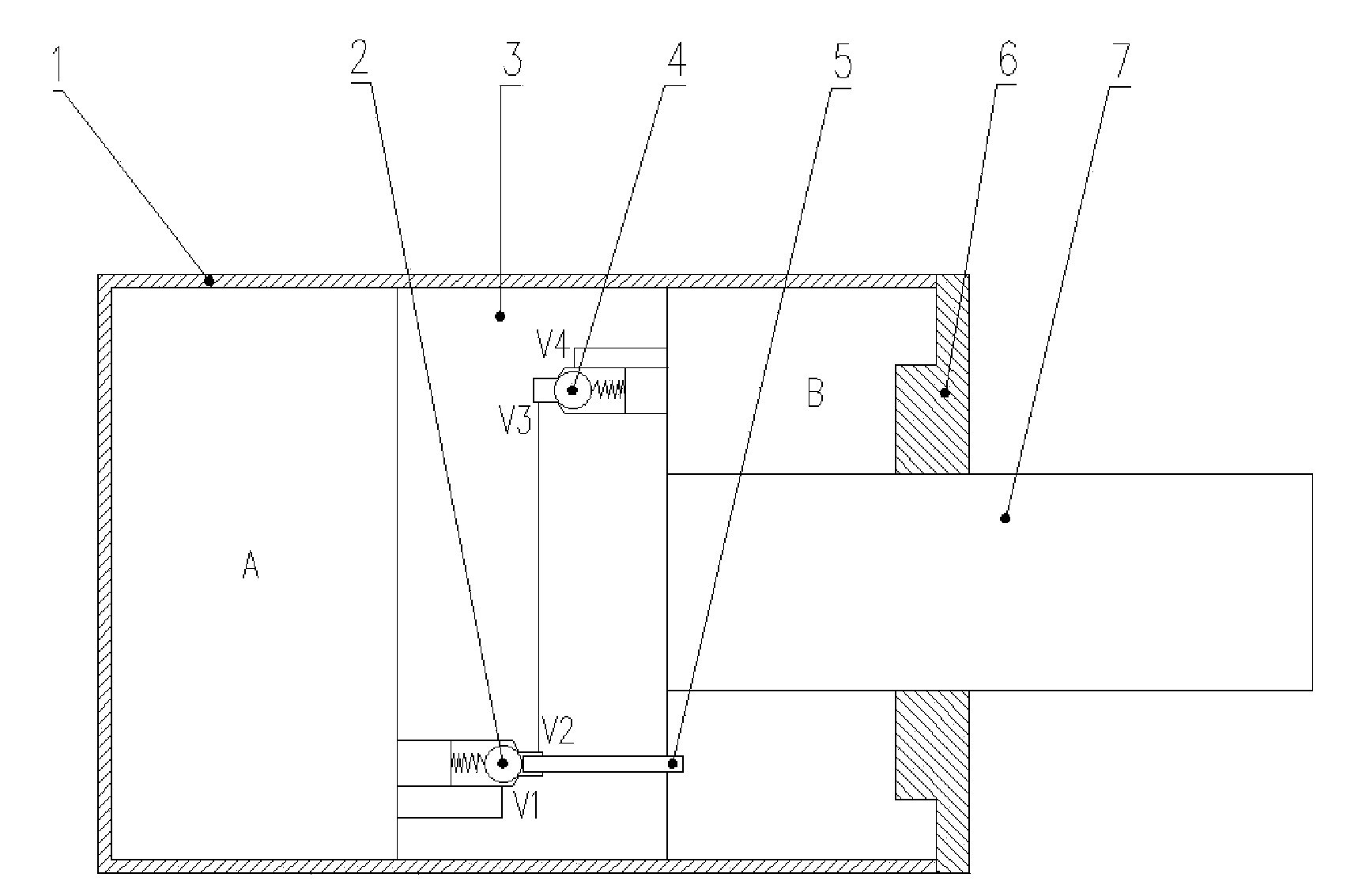
[0034] The invention provides a hydraulic cylinder, which is combined with figure 1 and figure 2 comparison, it can be seen that image 3 technical improvements in . Such as image 3 As shown, the present invention provides a hydraulic cylinder, comprising: a cylinder 1, a piston 3, a piston rod 7 and an end cover 6, the piston 3 is locate...


PUM


Abstract

The invention discloses a hydraulic cylinder, which comprises a cylinder tube, a piston, a piston rod and an end cap, wherein the piston is positioned in the cylinder tube and is used for separating the cylinder tube into a first cavity and a second cavity, the piston rod is positioned at one side of the piston and is fixedly connected with the piston, the end cap is fixedly connected with an opening port of the cylinder tube, the piston rod penetrates out of the end cap, the piston is provided with a limiting device, the limiting device comprises a first one-way valve, a second one-way valve and a first push rod, an oil outlet of the first one-way valve is communicated with a first cavity, an oil inlet of the first one-way valve is communicated with an oil inlet of the second one-way valve, an oil outlet of the second one-way valve is communicated with the second cavity, one end of the first push rod extends into the second cavity, the first push rod can slide along the cylinder tube in the axial direction, and then the other end of the first push rod jacks up a valve core of the first one-way valve. The hydraulic cylinder has the advantages that the power in the piston movement process is reduced, and the piston is prevented from colliding with the end cap or the bottom wall of the cylinder tube, so the cylinder tube is protected.

Description

technical field [0001] The invention relates to a hydraulic cylinder, in particular to a hydraulic cylinder with a limit device for automatically reducing the power of the hydraulic cylinder. Background technique [0002] Hydraulic cylinders are common hydraulic components in construction machinery. There are two common types in the prior art, such as figure 1 and figure 2 shown in . The hydraulic cylinder includes a cylinder 1, a piston 3, a piston rod 7 and an end cover 6. The piston 3 is located inside the cylinder 1 and divides the cylinder 1 into a first chamber A and a second chamber B. The piston rod 7 is located on one side of the piston 3 and is fixedly connected with the piston 3, the end cover 6 is fixedly connected with the open end of the cylinder barrel 1, and the piston rod 7 extends through the end cover 6. out. figure 1 In the hydraulic cylinder, when the piston 3 moves toward the right side, the pressure oil action area during the full stroke of the p...

Claims


Application Information

Patent Timeline
Patent Type & Authority Applications(China)
IPC IPC(8): F15B15/24F15B15/14
Inventor 涂书柏张华王从振孟钦定
Owner 河北雷萨重型工程机械有限责任公司
Why Eureka
Try Eureka