
Viscosity reducing effect evaluation method and device of heavy oil viscosity reducer under stratum seepage condition

A technology of viscosity reducer and evaluation device for heavy oil, which is used in the fields of production of fluid, earth-moving drilling and production, wellbore/well components, etc.

Active Publication Date: 2013-12-18
CHINA UNIV OF PETROLEUM (EAST CHINA)
View PDF6 Cites 10 Cited by
  • Summary
  • Abstract
  • Description
  • Claims
  • Application Information

AI Technical Summary

Problems solved by technology

Therefore, the same method cannot be used for the evaluation of the viscosity-reducing agent under the pipe flow condition and the evaluation of the viscosity-reducing agent under the percolation condition.

Method used


Image

  • Viscosity reducing effect evaluation method and device of heavy oil viscosity reducer under stratum seepage condition

Examples


Embodiment 1

[0038] Example 1: Evaluation of the viscosity-reducing effect of oil-soluble viscosity reducer under formation seepage conditions

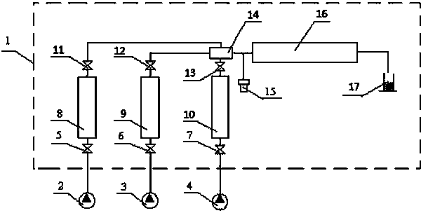
[0039] (a) Take 500mL of crude oil and simulated formation water with a salinity of 10000mg / L and add them respectively figure 1 Standby in the first high-pressure vessel (8) and the second high-pressure vessel (9) in the

[0040] (b) According to the concentration requirements of the viscosity reducer, add a viscosity reducer SLD with a mass concentration of 1% in the crude oil (the viscosity reducer SLD is a product that can be purchased in the existing market), mix well, and add it to the third high-pressure vessel 10 spare;

[0041] (c) According to the permeability of the target formation, select core 16, the diameter of the core is 2.54cm, the length is 20cm, and the gas permeability is 635×10 -3 μm 2 ;

[0042] (d) Adjust the temperature of the thermostat 1 to 70°C, keep the temperature constant for 8 hours, and simulate the formation...

Embodiment 2

[0052] Example 2: Evaluation of the viscosity-reducing effect of water-soluble viscosity reducer under formation seepage conditions

[0053] (a) Take 500mL of crude oil and simulated formation water with a salinity of 10000mg / L and add them respectively figure 1 Standby in the first high-pressure vessel (8) and the second high-pressure vessel (9) in the

[0054] (b) According to the concentration requirements of the viscosity reducer, add the viscosity reducer HED with a mass concentration of 1% in the simulated formation water (the viscosity reducer HED is a product that can be purchased in the existing market), mix well, and add the third high-pressure vessel 10 in standby;

[0055] (c) According to the permeability of the target formation, select core 16, the diameter of the core is 2.54cm, the length is 20cm, and the gas permeability is 686×10 -3 μm 2 ;

[0056] (d) Adjust the temperature of the thermostat 1 to 70°C, keep the temperature constant for 8 hours, and sim...


PUM


Abstract

The invention relates to a technology of oil-gas field development, particularly to a viscosity reducing effect evaluation method and device of heavy oil viscosity reducer under the stratum seepage condition. The method comprises the steps of determining the permeability rate and the experimental temperature according to the stratum condition, simultaneously injecting oil and water into a rock core in proportion through a seepage experiment and according to the water content, performing seepage experiment, recording the seepage pressure difference variation, evaluating the influence on oil and water stratum resistance by the viscosity reducer, calculating the apparent viscosity according to the Darcy law, comparing the variations of apparent viscosities of oil and water before and after the viscosity reducer is added, and evaluating the viscosity reducing effect of the viscosity reducer and the influence on the stratum seepage resistance by the viscosity reducer under the stratum seepage condition. The technology considers the difference of oil-water mixture in the conditions of stratum seepage and pipe flow, embodies the influence of a pore structure and a phase interface during the stratum seepage process, and is applicable to the evaluation of the heavy oil viscosity reducer under the stratum seepage condition.

Description

technical field [0001] The invention relates to an oil and gas field development technology, in particular to a method and device for evaluating the viscosity-reducing effect of a heavy oil viscosity-reducing agent under formation seepage conditions. Background technique [0002] At present, with the decrease of conventional crude oil, the exploitation of heavy oil occupies a very important position in crude oil production. my country's heavy oil resources are very rich and widely distributed, and its total resources account for about 25% to 30% of the total oil reserves. However, due to the high viscosity and poor fluidity of heavy oil, its exploitation and utilization are greatly restricted. Heavy oil has two basic flow processes in the production process: the formation seepage process from the formation to the bottom of the well; the flow process from the bottom of the well to the wellhead and the pipe flow process from the wellhead to the combined station or storage ta...

Claims


Application Information

Patent Timeline
IPC IPC(8): E21B49/00E21B43/22
Inventor 李宾飞李兆敏孙晓娜吴信荣史江恒李松岩王鹏
Owner CHINA UNIV OF PETROLEUM (EAST CHINA)
Learn More