Self-closing culture cage
A breeding box and self-collection technology, which is applied in fish farming, devices for catching or killing insects, engine components, etc., can solve the problems of aquatic products escaping, and achieve the effect of reducing accidental losses
- Summary
- Abstract
- Description
- Claims
- Application Information
AI Technical Summary
Problems solved by technology
Method used
Image
Examples
Embodiment 1
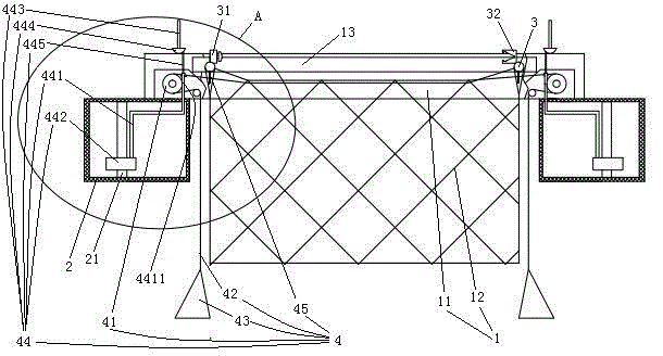
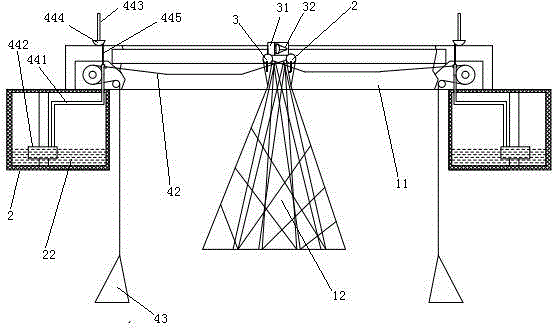
[0024] Embodiment one, see figure 1 , a self-closing type breeding box, including a net cage 1, a floating box 2 and a closing rod 3.
[0025] Net cage 1 comprises support frame 11 and the culture net 12 of upper end opening. The support frame 11 is a square ring when viewed from above. The front and rear sides of the support frame 11 are provided with sliding holes 13 extending along the left and right directions.
[0026] There are four floating tanks 2. The floating tank 2 is a closed structure. Four buoyant tanks 2 are connected at the four corners of support frame 11.
[0027] Closing bar 3 has a pair and is parallel. The closing rod 3 extends along the front-to-back direction. The front and rear ends of the closing rod 3 are pierced and slidably connected in the sliding hole 13 . The left and right sides of the upper end of the breeding net 12 are correspondingly fixed on two closing rods 3 . One of the pair of closing rods 3 is provided with a locking block 31 ,...
Embodiment 2
[0033] Embodiment two, see Figure 4 The difference with the first embodiment is that it also includes a power coupling mechanism 5, a generator 6, a storage battery 61 and a water electrolyzer 7 connected in sequence. A wave-dissipating wall 15 is provided on the support frame 11 . Oxygen produced by the water electrolysis cell 7 is collected in an oxygen tank 71 . The air outlet of oxygen tank 71 is connected together with the air inlet of air pump 73. The gas outlet of air pump 73 is connected together with the inlet end of oxygen pipe 74. The outlet end of oxygen pipe 74 is inserted in the net cage 1. The hydrogen produced by the water electrolyzer 7 is collected in a hydrogen tank 72 . Hydrogen tank 72 is connected together with gas lamp 9 by hydrogen pipe 91. Gas lamp 9 is positioned at the top of net box 1.
[0034] The wave-dissipating wall 15 is arranged obliquely. On the wave-facing side of the wave-dissipating wall 15 are provided several wave-resistant strip...
Embodiment 3
[0041] Embodiment three, see Figure 7 , The difference with the second embodiment is: there is only one floating tank 2 and it surrounds the culture net 1 around. A closing rod (that is, the closing rod on the right side in the figure) is fixed on the support frame 11 in a pair of closing rods 3 .
[0042] An annular cavity 16 is provided on the support frame 11 . The annular cavity 16 is provided with a water inlet 161 . The water inlet 161 is located on the inner peripheral surface of the annular cavity 161 . The submerged depth detection rod 443 of the support frame and the second float 444 are located in the annular cavity 16 . It can prevent wave interference and cause malfunction. Obviously, the same effect can also be achieved in the case of Embodiment 1 in combination with the solution described in this paragraph.
PUM
 Abstract
Description
Claims
Application Information
 - R&D
- Intellectual Property
- Life Sciences
- Materials
- Tech Scout
- Unparalleled Data Quality
- Higher Quality Content
- 60% Fewer Hallucinations
Browse by: Latest US Patents, China's latest patents, Technical Efficacy Thesaurus, Application Domain, Technology Topic, Popular Technical Reports.
© 2025 PatSnap. All rights reserved.Legal|Privacy policy|Modern Slavery Act Transparency Statement|Sitemap|About US| Contact US: help@patsnap.com


