Device for measuring railway vehicle end relation

A technology of car-end relationship and rail vehicle, applied in the field of devices for measuring the relationship between rail vehicles Flexible and convenient, meet the requirements of stiffness test, and easy to adjust the installation position

Active Publication Date: 2013-12-11
CRRC CHANGCHUN RAILWAY VEHICLES CO LTD +1
View PDF7 Cites 13 Cited by
  • Summary
  • Abstract
  • Description
  • Claims
  • Application Information

AI Technical Summary

Problems solved by technology

[0004] At present, the existing achievements of the vehicle-end relationship test device include: the invention name is "rail vehicle vehicle-end relationship comprehensive test bench", the applicant is Jilin University, and the Chinese patent authorization announcement number is 102226743A. The disadvantage is that it is inconvenient to disassemble and assemble, and the system rigidity is low.
The name of the invention is "Comprehensive Test Bench for Vehicle-End Relationship", the applicant is Harbin Institute of Technology, and the Chinese patent authorization announcement number is 102128723A. It is very inconvenient to install, use, transport and store, and has poor versatility. inconvenient
Moreover, it cannot realize the detection of the windshield force of the coupler and the end wall of the vehicle, and cannot realize a more realistic two-way loading simulation on the end of the vehicle, so it cannot truly reflect the state and relationship of each component when the vehicle passes through the curve.

Method used


Image

  • Device for measuring railway vehicle end relation
  • Device for measuring railway vehicle end relation
  • Device for measuring railway vehicle end relation

Examples


Embodiment Construction

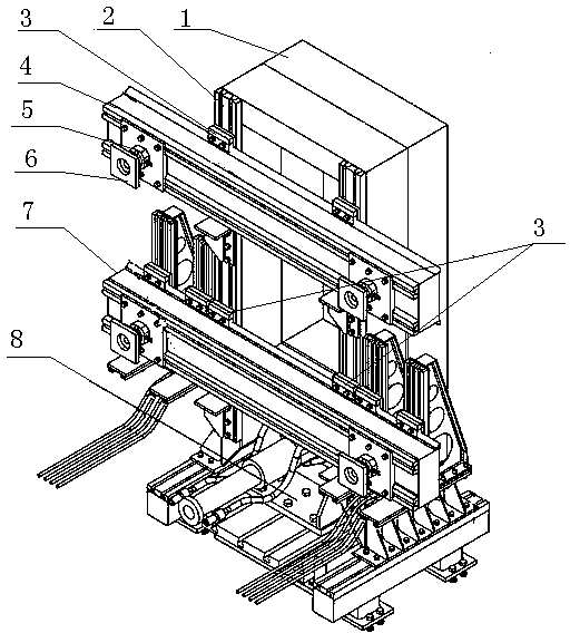
[0031] refer to figure 1 , the device for measuring the relationship between the vehicle end in the embodiment of the present invention is composed of the upper door frame dovetail guide rail beam device 4, the lower door frame dovetail guide rail beam device 7, the coupler reaction force hinge seat assembly 8 and the vehicle end wall fixing device 1, The upper door frame dovetail guide rail beam device is adjustable up and down connected with the T-slot guide rail 2 in front of the vehicle end wall fixing device 1 through the bead assembly 3, and the lower door frame dovetail guide rail beam device is also fixed with the vehicle end wall through the bead assembly 3 The T-slot guide rails 2 in front of the device are adjustable up and down, and the whole device is arranged in pairs, and the three-dimensional force sensor 5 on the front side of the upper door frame dovetail guide rail beam device and the lower door frame dovetail guide rail beam device is connected to the vehicl...


PUM


Abstract

A device for measuring a railway vehicle end relation is characterized in that the device comprises an upper n-shaped frame dovetail guide rail beam device, a lower n-shaped frame dovetail guide rail beam device, a draw gear counter-force hinge base assembly and a vehicle end wall fixing device, the upper n-shaped frame dovetail guide rail beam device is connected with a T-shaped groove guide rail in front of the vehicle end wall fixing device through a pressing bar assembly, the lower n-shaped frame dovetail guide rail beam device is connected with a T-shaped groove guide rail in front of the vehicle end wall fixing device through a pressing bar assembly as well, the parts of the overall device are arranged in pairs oppositely, and vehicle end connecting boards on the front side faces of the upper n-shaped frame dovetail guide rail beam device and the lower n-shaped frame dovetail guide rail beam device are used for clamping a vehicle body in an experiment. According to the device for measuring the railway vehicle end relation, connection can be completed according to different structures and sizes of draw gears, the interference force detection of the draw gears, the detection of the windshield acting force and the force moment of a vehicle end wall and the detection of the acting force and the force moment of a vehicle end electric cable can be completed; disassembly, assembly, combination and adjustment of a door are flexible and convenient, an gantry is large in overall rigidity, the requirements of rigidity tests can be satisfied, the adjustment of electric cable connecting points between trains is convenient, and the installation position of a force cell is conveniently adjusted.

Description

technical field [0001] The present invention relates to a device for measuring the relationship between rail vehicle ends, more specifically, the present invention relates to a device that simulates the movement interference test, functional test and Device for research experiments. Background technique [0002] The car end is an indispensable and important device in the composition of rail vehicles, which plays the role of connecting each car and making it pass through various curves and curves smoothly under the drive of the train. The performance of the train end directly affects the running quality and safety of the EMU train. The car end relationship test refers to the relative movement and rotation of the parts installed at the end of the car body during the operation of the train due to the relative movement and rotation of the parts of the train body and when passing through the curve. By measuring the displacement and force of the parts To measure the stiffness an...

Claims


Application Information

Patent Timeline
IPC IPC(8): G01M17/08
Inventor 王金田谭富星苏建宋建林慧英杨小敏朱彦滕万秀刘洪涛张益瑞杜志豪王秀刚王启明刘雪峰张兰
Owner CRRC CHANGCHUN RAILWAY VEHICLES CO LTD
Why Eureka
Try Eureka