
Downhole pneumatic shock wave generator

A generator and shock wave technology, applied in wellbore/well components, earthwork drilling, etc., can solve the problems of reduced working life, incomplete function, accelerated shock wave generator damage, etc., to improve efficiency and increase service life. Effect

Inactive Publication Date: 2013-12-11
CHINA UNIV OF GEOSCIENCES (WUHAN)
View PDF4 Cites 1 Cited by
  • Summary
  • Abstract
  • Description
  • Claims
  • Application Information

AI Technical Summary

Problems solved by technology

[0004] The currently known pneumatic shock wave generators have the following problems: 1) After the high-pressure gas pulse is ejected, there is no shield around it, which produces a certain amount of divergence, so that the impact energy of the high-pressure gas cannot fully act on the blockage, resulting in waste of energy and inefficiency
2) The divergent high-pressure gas may push the pneumatic shock wave generator to move, resulting in collision with the screen tube, accelerating the damage of the shock wave generator and reducing its working life
Especially in flammable and explosive formations such as natural gas, the collision between the shock wave generator and the screen may generate sparks and cause major safety accidents such as explosions

Method used


Image

  • Downhole pneumatic shock wave generator

Examples


Embodiment Construction

[0014] The present invention will be described in detail below in conjunction with the accompanying drawings. The following content is a further detailed description of the present invention in conjunction with specific preferred embodiments. It cannot be assumed that the specific implementation of the present invention is only limited to these descriptions. Those of ordinary skill in the technical field of the present invention can also make some simple deduction or replacement without departing from the concept of the present invention, and the above structures should all belong to the protection scope of the present invention.

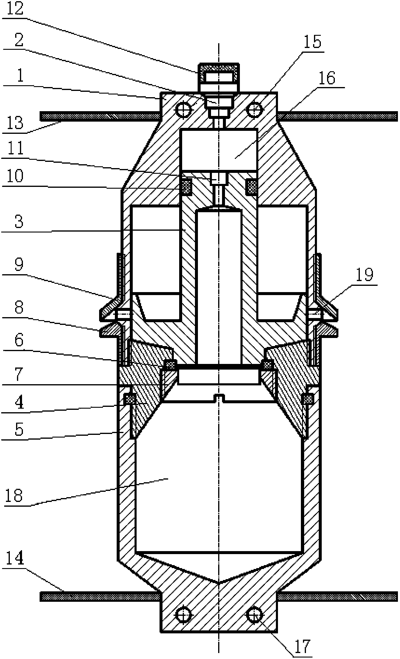
[0015] The overall structure of the pneumatic shock wave generator provided in this embodiment is as follows: figure 1 As shown, at least the generator body is included. The upper and lower parts of the generator body are respectively provided with an upper shock wave reflection device 13 and a lower shock wave reflection device 14. The upper shock w...


PUM


Abstract

The invention provides a downhole pneumatic shock wave generator, which at least comprises a generator body, a top shock wave reflector and a bottom shock wave reflector, which are elastic parts, are respectively arranged on the top and bottom of the generator body, and moreover, the top shock wave reflector and the bottom shock wave reflector are arranged on the left side and right side of the generator body, and are used for isolating the generator body from the well wall; the generator body at least comprises a housing, a duct, a nipple, a support and a piston, a movable ring A and a movable ring B are also sleeved on the outer wall of the housing, wherein the movable ring A is located under vent holes, and the movable ring B is located over the vent holes. The structure of the pneumatic shock wave generator is simple, the service life is long, and the defects of the background art are solved. The service life of the pneumatic shock wave generator can be prolonged, and moreover, the generated air shock wave is concentrated.

Description

technical field [0001] The invention relates to an underground pneumatic shock wave generator, which is used for removing silt during the mining of fluid minerals and increasing the output of fluid minerals. Background technique [0002] Fluid resources such as oil and gas are an important part of the national strategic resource reserve, so it is necessary to improve production efficiency in all aspects of exploration, development, and collection. At present, the common production plan for fluid resources such as oil and gas is to construct exploration wells first to determine the distribution and reserves of oil and gas fields. Secondly, in the construction of development wells, directional wells and other technologies are used to allow the wellbore of the entire development well to pass through the oil and gas layer as long as possible. The pressure difference allows the oil and gas resources to flow out from the fractures in the formation and enter the development wellbo...

Claims


Application Information

Patent Timeline
Patent Type & Authority Applications(China)
IPC IPC(8): E21B31/107
Inventor 契霍特金V·F段隆臣李谦汤凤林庞丰
Owner CHINA UNIV OF GEOSCIENCES (WUHAN)
Learn More