
Permanent magnet plane gear mechanism

A technology of gear mechanism and permanent magnet plane, which is applied in the direction of electromechanical devices, electromechanical transmission devices, electrical components, etc., and can solve problems such as low assembly accuracy requirements and complex tooth profiles of large gear plates

Inactive Publication Date: 2013-12-04
DALIAN UNIV OF TECH
View PDF4 Cites 9 Cited by
  • Summary
  • Abstract
  • Description
  • Claims
  • Application Information

AI Technical Summary

Problems solved by technology

Ordinary mechanical face gears use a small ordinary cylindrical spur gear to mesh with a large gear plate in an orthogonal layout. It has the advantages of low assembly accuracy requirements and simple pinion gears, but the tooth profile of the large gear plate is complicated.

Method used


Image

  • Permanent magnet plane gear mechanism
  • Permanent magnet plane gear mechanism

Examples


Embodiment Construction

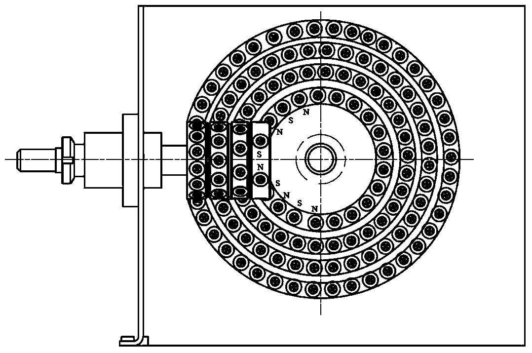
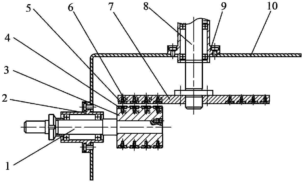
[0012] The specific embodiment of the present invention is described in detail in conjunction with technical scheme and accompanying drawing: For the attached figure 1 and attached figure 2 The permanent magnet plane gear mechanism shown is composed of a drive shaft 1, a drive shaft with seat bearing 2, a small cylindrical wheel 3, an S pole permanent magnet block 4, an N pole permanent magnet block 5, a fixing screw 6, a large disc 7, Driven shaft 8, driven shaft belt seat bearing 9 and support 10 are formed.

[0013] The small cylindrical wheel 3 is installed and fixed on the left end of the driving shaft 1, and the large disc 7 is installed and fixed on the front end of the driven shaft 8. The driving shaft 1 is constrained to rotate through the driving shaft bearing 2; the driven shaft 8 is passed through the driven shaft with a seat. Bearing 9 constrains rotation. The drive shaft bearing seat 2 and the driven shaft bearing seat 9 are installed on the support 10 so that...


PUM


Abstract

The invention discloses a permanent magnet plane gear mechanism. The axis of a small cylindrical wheel is in orthogonal layout with the axis of a big round disc. A plurality of circles of concentric permanent magnet blocks are evenly distributed on the plane of the big round disc. A plurality of circles of permanent magnet blocks which have equal diameters and have the opposite polarity with the permanent magnet blocks on the big round disc are correspondingly and coaxially arranged on the cylindrical surface of the small cylindrical wheel. When the permanent magnet plane gear mechanism works, the positions of the minimum air gaps generated when the permanent magnet blocks on the small cylindrical wheel are meshed with the permanent magnet blocks on the big round disc are mutually aligned. A plurality of permanent magnet blocks on a plurality of sets of meshing pairs participate in meshing and the meshing time is non-synchronous. Therefore, the permanent magnet plane gear mechanism not only improves driving torque, but also improves driving stationarity under the condition of loading. In addition, the same round permanent magnet blocks are adopted in the two permanent magnet gears, the manufacturing difficulty of magnetic pole blocks and the permanent magnet gears is reduced.

Description

technical field [0001] The invention relates to a permanent magnet gear transmission mechanism, in particular to a permanent magnet plane gear transmission mechanism with an input shaft and an output shaft orthogonal to each other. Background technique [0002] Permanent magnet gears are driven by coupled magnetic fields. With the widespread use of high-performance NdFeB permanent magnet materials, permanent magnet gears have gradually attracted attention. Compared with traditional mechanical gears, permanent magnet gear transmission has non-contact, no wear, Advantages of maintenance-free, low noise, overload protection and low assembly precision. However, the transmission torque is relatively small, and the permanent magnet gear transmission is divided into external meshing transmission, internal meshing transmission and rack and pinion transmission. Their structure is generally a torus or cylinder of permanent magnets distributed alternately in the radial direction, and ...

Claims


Application Information

Patent Timeline
IPC IPC(8): H02K51/00
Inventor 戴恒震赵文秀高鹏李昊宇
Owner DALIAN UNIV OF TECH
Learn More