
An optical current sensor and high-frequency signal measurement system

A current sensor and optical sensing technology, applied in the direction of voltage/current isolation, measurement using digital measurement technology, etc., to achieve the effect of convenient daily maintenance and replacement, avoiding potential safety hazards, and simple structure

Active Publication Date: 2015-10-21
泰安泰山高压开关有限公司
View PDF9 Cites 0 Cited by
  • Summary
  • Abstract
  • Description
  • Claims
  • Application Information

AI Technical Summary

Problems solved by technology

[0005] The present invention aims at the problem that neither the traditional current sensor nor the conventional optical current sensor of the current power system is suitable for measuring high-frequency signals under high-voltage and high-current conditions, and provides a new type of optical current sensor, which can complete the measurement of high-frequency signals, Improve measurement accuracy and reliability

Method used


Image

  • An optical current sensor and high-frequency signal measurement system
  • An optical current sensor and high-frequency signal measurement system
  • An optical current sensor and high-frequency signal measurement system

Examples


Embodiment Construction

[0033] The present invention will be described below in conjunction with the accompanying drawings.

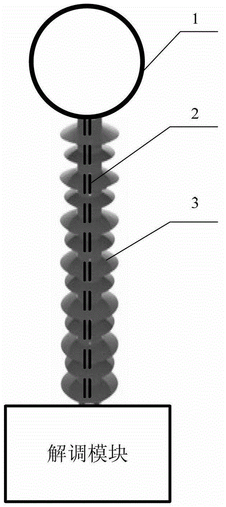
[0034] The invention relates to an optical current sensor, which is used for current measurement in a power system, especially for high-voltage and high-current high-frequency current measurement, such as high-voltage busbar or high-frequency current measurement on electrodes. The structure of the optical current sensor is as figure 1 As shown, it includes an optical sensing component 1, a polarization maintaining optical fiber 2, an insulator 3 and a demodulation module, wherein the optical sensing component 1, a polarization maintaining optical fiber 2 and a demodulation module are connected in sequence, and the optical sensing component 1 is supported by an insulator 3 , the polarization maintaining optical fiber 2 is located in the cavity of the insulator 3, and the cavity of the insulator 3 is filled with an insulating medium. The material of the insulator 3 in high freq...


PUM


Abstract

The invention relates to an optical current sensor and a high-frequency signal measurement system. The optical current sensor comprises an optical sensing part, a polarization maintaining fiber, an insulator and a demodulation module. The optical sensing part, the polarization maintaining fiber and the demodulation module are connected in sequence. The optical sensing part is supported by the insulator. The polarization maintaining fiber locates in an inner cavity of the insulator. The optical sensing part comprises a first sensing fiber ring, a second sensing fiber ring, a first wave plate, a first reflector, a second wave plate, a second reflector and a support, wherein the first wave plate, the first reflector, the second wave plate, the second reflector and the support are all made of nonmetal material. The first sensing fiber ring and the second sensing fiber ring are opposite in current direction. The demodulation module outputs two linearly-polarized beams passing the polarization maintaining fiber and the optical sensing part, the linearly-polarized beams carrying measured current information are returned and received by the polarization maintaining fiber, the beams are operated on the basis of differential induction, and measured current is obtained. The optical current sensor is capable of measuring high-frequency signals, and measurement is higher in accuracy and reliability.

Description

technical field [0001] The invention relates to the technical field of power equipment, in particular to an optical current sensor and a high-frequency signal measurement system using the optical current sensor. Background technique [0002] The current sensor is an important device for relay protection and electric energy metering in the power system. It is used to measure the current in transmission and send the measured current to the measuring instrument and relay protection device. Its long-term stability, reliability, and security are closely related to the safe and stable operation of the power system. The current sensors currently used in the power system are mainly based on the principle of electromagnetic induction, which will induce energy from the primary current. The traditional current sensor based on this principle works at low frequencies (such as 50Hz) and when the voltage is not too high. If it is not too large, it can meet the demand. When the current sen...

Claims


Application Information

Patent Timeline
Patent Type & Authority Patents(China)
IPC IPC(8): G01R19/25G01R15/24
Inventor 周炜
Owner 泰安泰山高压开关有限公司
Learn More