
Full-drive leveler

A leveler and full-drive technology, applied in the field of full-drive levelling (leveling) machines, can solve problems such as excessive load on the transmission shaft and twisted and twisted work rolls.

Active Publication Date: 2015-04-08
南通海迅智造科技股份有限公司
View PDF7 Cites 0 Cited by
  • Summary
  • Abstract
  • Description
  • Claims
  • Application Information

AI Technical Summary

Problems solved by technology

[0003] The present invention aims to overcome the above-mentioned defects, and provides a full-drive leveler, which can not only solve the serious twisting phenomenon of slender work rolls and the transmission The technical problem of excessive shaft load can save energy; specifically, the full-drive leveler includes a main power system and an auxiliary power system, and the main power system includes a main motor, a reducer, a distribution box, a transmission shaft and a work roll, The transmission system of the auxiliary power system includes a reducer, a distribution box and a transmission shaft; the leveler also includes an automatic control system, a torque monitoring sensor is installed on the work roll, and a load monitoring sensor is installed on the transmission shaft of the main power system. The sensors will send the monitored data signals to the automatic control system; in the first working state of the leveler, that is, when the flatness of the plate is not high and the state of the plate surface is relatively good, only the active power system needs to be turned on; Two working conditions, that is, when the torque monitoring sensor installed on the work roll or the load monitoring sensor installed on the drive shaft detects that the data signal exceeds the expected value, the auxiliary power system is turned on; after the auxiliary power system is turned on, when any sensor monitors the data When the signal still exceeds the expected value, the automatic control system issues an alarm and shuts down the leveler after a period of time, which is 1 minute, 3 minutes or 5 minutes

Method used


Image

  • Full-drive leveler

Examples


Embodiment Construction

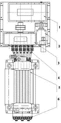
[0006] Refer to attached figure 1 , The full-drive leveler according to the present invention includes a main motor 2, a reducer 1, a distribution box 3, a transmission shaft 4, a work roll 5 (the above may be referred to as the main power system) and an auxiliary power system 6. The transmission shaft 4 can be, for example, a universal joint or a universal joint. The auxiliary power system 6 may include a hydraulic motor or a special motor, and its transmission system may also be similar to the main power system, including a reducer, a distribution box and a transmission shaft. Preferably, the full-drive leveler according to the present invention also includes an automatic control system, a torque monitoring sensor is set on the work roll, and a load monitoring sensor is set on the transmission shaft, and both sensors will send the monitored data signals to the automatic control system system; in the normal and normal working state of the leveler (that is, the flatness of t...


PUM


Abstract

A full-drive leveler, including main motor, reducer, distribution box, transmission shaft, work roll and auxiliary power system, also includes automatic control system, torque monitoring sensor is set on the work roll, and load monitoring is set on the drive shaft These two sensors will send the monitored data signals to the automatic control system; the automatic control system will control the full-drive leveler according to the data signals detected by the torque monitoring sensor set on the work roll or the load monitoring sensor set on the transmission shaft. run. The full-drive leveler according to the invention can not only solve the problems of severe twisting phenomenon of slender work rolls and excessive load of the transmission shaft, but also save energy.

Description

technical field [0001] The invention relates to a full-drive leveling (leveling) machine, in particular to a roller-type plate leveling (leveling) machine in which power is input to both ends of a work roll. Background technique [0002] The driving power for leveling (calibration) leveling of the traditional roller plate leveling machine is basically set at one end of the work roll, or placed at both ends to drive the upper and lower row of work rolls respectively. When straightening (levelling) metal plates with high flatness requirements and particularly poor surface conditions, it is necessary to increase the overlap of the upper and lower rollers and increase the leveling (correction) pressure. It is required that the drive shaft can transmit more torque to overcome the resistance between the work roll and the material to be calibrated. Due to the constraints of the center distance of the work rolls and the material and structure, the load capacity of the transmission ...

Claims


Application Information

Patent Timeline
Patent Type & Authority Patents(China)
IPC IPC(8): B21D1/02
Inventor 刘广晶涂怀中
Owner 南通海迅智造科技股份有限公司
Learn More